


2. High-Voltage Adjustment (SN 3001A and Below)
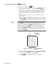
27. On the oscilloscope press
[SHOW].
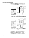
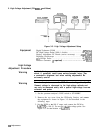
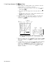
28. Connect the oscilloscope channel 1 probe to AlA3TP5 using a long
probe extension. See Figure 3-7 for the location of AlA3TP5.
29. Reconnect the ac line cords to each instrument section. Adjust
the front-panel INTENSITY control fully counter-clockwise, and
then set the LINE switch to ON (the INSTR CHECK I LED will
light.)
30. Wait approximately 30 seconds for the dc regulator circuits to
stabilize again.
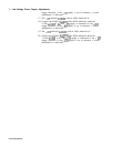
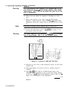
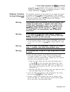
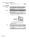
31. With the front-panel INTENSITY control fully counter clockwise,
adjust AlA2R35 INT LIMIT (clockwise) until a spot is just visible
in the lower left corner of the CRT. See Figure 3-8 for the location
of the adjustment.
Note
The AlA2R35 INT LIMIT adjustment compensates for the variation
in beam cut-off voltage of different CRTs and indirectly sets the
maximum beam intensity. AlA2R35 INT LIMIT should have enough
range to turn the CRT spot on and off. If the spot is always on,
decrease the value of AlA2R9. If the spot is always off, increase
the value of AlA2R9. Refer to Table 3-3 for the acceptable range of
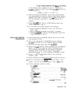
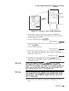
values, and to Table 3-4 for HP part numbers. Refer to Figure 3-8 for
the location of AlA2R9.
R35
R5
R36
INT
I
NT
ASTIG
LIMIT GAIN
R9
I
.//
/
Figure 3-8. Location of
AlA
Components
32. Using a non-metallic alignment tool, center the front panel FOCUS
control and adjust AlA2R36 ASTIG and AlA3R14 FOCUS LIMIT
for a sharp, focused dot on the CRT display.
33. Adjust AlA2R35 INT LIMIT until the dot just disappears.
3-34 Adjustments