


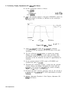
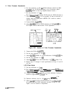

5. Log Amplifier Adjustments
4. Connect DVM to
A4AlTPl
and DVM ground to the IF casting.
Connect the frequency synthesizer to the RF INPUT. Key in
CFREQUENCY)
80 MHz and [AMPLITUDE) -86.98 dBm. The frequency
synthesizer will now provide a
5OfI
load.
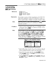
Offset Adjustment Check
5. Adjust
A4A2R79
ZERO for 0.0000
f0.0005
V dc. See Figure 3-34
for location of adjustment.
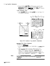
R79
R61
R91
R14
R62
ZERO
ATTEN
-12
VTV
LG 20
RI8
A4A3
A4A2
LOG
AMPLIFIER-
LOG AMPLIFIER-
FILTER
DETECTOR
\
I
A4A2
R83
c55
R67
LG 10
C52
C53
CTR
R66
AMPTD
A4A3
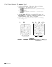
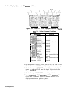
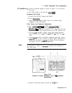
Figure 3-34. Location of Log Amplifier Adjustments
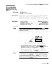
Bandpass
Filter Center Adjustment
6. Press LOG (ENTER
dB/DIv)
7. Set the frequency synthesizer for 7.6000 MHz at
+5.0
dBm output
level.
8. Adjust
A4A3C55
CTR for maximum DVM indication. See
Figure 3-34 for location of adjustment. If
A4A3C55
is at an
extreme of its adjustment range (fully meshed, maximum
capacitance, or unmeshed, minimum capacitance), increase or
decrease value of
A4A3C52
and
A4A3C53.
Refer to
‘able
3-3 for
range of values.
Note
A4A3C52
is a fine adjustment, and
A4A3C53
is a coarse adjustment.
If
A4A3C55
is fully meshed, increase the value of
A4A3C52
or
A4A3C53.
3.66
Adjustments