


8. Frequency Response
Test
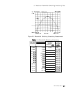
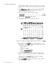
25. After completion of sweep, press DISPLAY LINE
(j?KiK]
on the
spectrum analyzer. Use the Display Line to measure the maximum
and minimum points on the trace. Record the measurements
below.
SIGNAL INPUT 1
(100 kHz to 20 MHz)
Maximum dBm
Minimum dBm
26. Measure and record signal level at start of trace (100
kHz).
SIGNAL INPUT 1
(100
kHz)
dBm
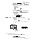
27. Connect output of frequency synthesizer to SIGNAL INPUT 2.
Activate this input with the pushbutton.
Option 001. Do not use HP
11852A
Minimum Loss Pad. Set
frequency synthesizer output amplitude to -2 dBm.
28. Press TRACE A
CCLEAR-WRITE)
and DISPLAY LINE
(OFF)
on
spectrum analyzer.
29. Set frequency synthesizer FREQUENCY to 20 MHz. Set spectrum
analyzer (CENTER FREQUENCY_) to 20 MHz, and (FREQUENCY SPAN) to
1 MHz.
30. Repeat steps 22 through 24.
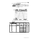
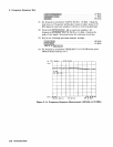
31. After completion of sweep, press DISPLAY LINE
[ENTER]
on the
spectrum analyzer. Use the Display Line to measure the maximum
and minimum points on the trace. Record the measurements
below.
SIGNAL INPUT 2
(100 kHz to 20 MHz)
Maximum
dBm
Minimum
dBm
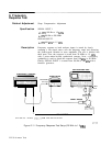
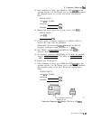
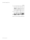
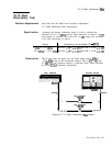
Figure 2-15.
Frequency Response
Test
Setup (100 Hz to 100
k=)
Performance Tests
2-27