


24. Track and Hold
Adjustments
Reference
A3A9
Track and Hold
Description
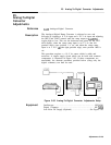
The CAL OUTPUT signal is connected to the RF INPUT. The
instrument is placed in zero frequency span to produce a dc level
output from the IF-Video section and this dc level is regulated by
adjusting the reference level. The Offsets and Gains on the Track and
Hold assembly are adjusted for proper levels using a DVM.
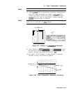
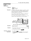
SPECTRUM
ANALYZER
DIGITAL
VDLTMETER
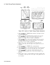
Figure 3-87. Track and Hold Adjustments Setup
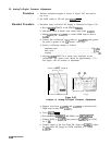
Equipment
Digital Voltmeter (DVM) . . . . . . . . . . . . . . . . . . . . . . . . . . . . . . HP
3456A
Procedure
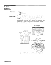
1. Place instrument upright as shown in Figure 3-87 with top and
A3
Digital Storage covers removed.
2. Set LINE switch to ON and press
(INSTR PRESET].
3. Connect CAL OUTPUT to RF INPUT.
4. Connect DVM to
A3A9TP3
and ground to A3A9TPl.
5. Key in
CCENTER
FREQUENCY) 20 MHz,
~FREQUENCY
SPAN] 0 Hz.
6. Disconnect cable 7 (violet) from
A4AlJl.
7. Short A3A9TPl to
A3A9TP3,
or use an SMB snap-on short to
A3A9Jl.
DVM indication should be 0.000
IfrO.001
V
de.
8. Key in
CRINGLE],
TRACE A (CLEAR-WRITE], MARKER
C-1,
MARKER
[nl,
SWEEP
(CONT),
(SHIFT_)
TRACE A
(BLANK)
e.
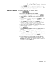
9. Adjust
A3A9R59
(T/H) OFS until MARKER
A
level indication as
indicated by CRT annotation flickers back and forth between .OO
and
.lO
dB.
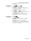
See Figure 3-88 for location of adjustment.
3-142 Adjustments