


8. Frequency Response Test
7.
8.
9.
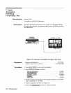
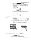
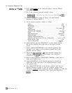
Key in the following spectrum analyzer settings:
10.
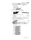
Press TRACE A
[MAX)
on the analyzer.
11.
Press SWEEP SINGLE on the synthesized sweeper.
Adjust POWER LEVEL on synthesized sweeper (using data knob)
to place peak of 20 MHz signal near reference level (top) graticule
line.
Press
[ENTER
dB/mv],
1
dB
on spectrum analyzer. Adjust POWER
LEVEL on synthesized sweeper to position peak of signal 2
divisions below the reference level line.
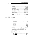
START FREQ)
. . . . . . . . . . . . . . . . . . . . . . . . . . . . . . . . . . . . . . . . . . . . . .
20.MHz
km)
. . . . . . . . .
..__..................................
1.5GHz
rp
REF
.0
darn
ATTEN
10
dB
I
dB/
I
I
DL
-.B
dBm
,
I
START
20
nnz
STOP
1500
MHZ
RES
BW
3
Mnt
VBW
1
MHZ
SWP
20
mssc
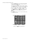
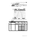
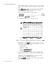
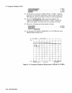
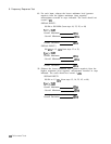
Figure 2-12. Frequency Response Measurement (20 MHz to 1.5
GHz)
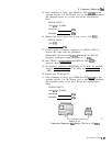
12. Press DISPLAY LINE
[ENTER)
on the spectrum analyzer. Use the
Display Line to measure the maximum and minimum points on the
trace. Record measurements below.
SIGNAL INPUT 2
(20 MHz to 1.5
GHz)
Maximum
dBm
Minimum
dBm
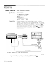
13. To check SIGNAL INPUT 1, use the type N male to BNC male
adapter to connect the power splitter directly to SIGNAL INPUT
1.
Option 001: Use HP
11852A
Minimum Loss Pad and adapters
between splitter and spectrum analyzer input.
14. Press
[INSTR PRESET) on spectrum analyzer, then activate SIGNAL
INPUT 1 with the pushbutton.
2-24 Performance Tests