


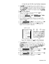

10. Step Gain and 18.4 MHz Local Oscillator Adjustments
10. If
A4A5R33
CAL adjustment does not have sufficient range to
adjust trace to the top CRT graticule line, increase or decrease the
value of
A4A7R60
as necessary to achieve the proper adjustment
range of
A4A5
CAL adjustment. See Figure 3-39 for the location
of
A4A7R60.
Refer to Table 3-3 for range of values for
A4A7R60.
10
dB
Gain Step Adjustment
11. Connect CAL OUTPUT to RF INPUT through 10
dB
step
attenuator and 1
dB
step attenuator.
12. Key in LOG (ENTER
dB/DIv]
1 dB and [REFERENCE LEVEL) -30 dBm.
13. Set step attenuators to 25
dB.
14. Key in MARKER A. Signal trace should be at the center CRT
graticule line, and MKR A level, as indicated by CRT annotation,
should be .OO
dB.
15. Key in [REFERENCE LEVEL] -40 dBm. Set step attenuators to 35
dB.
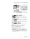
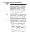
16. Adjust
A4A5R32
SGlO
for MKR A level of .OO
dB
(CRT MKR A
annotation is now in upper right corner of CRT display). See
Figure 3-48 for location of adjustment.
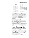
A4A5
STEP
LAIN
R32
R44 R54
SGIO
SG20-
1
R70
R62
A4A5
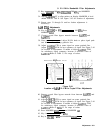
Figure 3-48. Location of 10
dB
Gain Step Adjustments
17. If
A4A5R32
SGlO
adjustment does not have sufficient range to
perform adjustment in step 16, increase or decrease the value of
A4A7R60
as necessary to achieve the proper adjustment range of
A4A5
SGlO.
See Figure 3-39 for the location of
A4A7R60.
Refer
to
‘Ihble
3-3 for range of values for
A4A7R60.
Repeat steps 3
through 16 if the value of
A4A7R60
is changed.
18. Key in [REFERENCE LEVEL] -50 dBm. Set step attenuators to 45
dB.
19. Adjust
A4A5R44
SG20-1
for MKR A level of .OO
dB.
See
Figure 3-48 for location of adjustment.
20. Key in
CREFERENCE
LEVEL) -70 dBm. Set step attenuators to 65
dB.
21. Adjust
A4A5R54
SG20-2
for MKR A level of .OO
dB.
See
Figure 3-48 for location of adjustment.
Adjustments 3-89