


Procedure
Second IF Amplifier
Adjustments
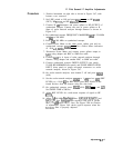
16. Second IF Amplifier and Third Converter Adjustment
Adapters:
Type N (f) to APC-3.5 (f) . . . . . . . . . . . . . . . . . . . . . . 1250-1745
Type N (m) to BNC (f)
(2
required) . . . . . . . . . . . . .
1250-0780
Type N (f) to BNC (f)
(2
required) . . . . . . . . . . . . . .
1250-1474
APC 3.5 (f) to APC 3.5 (f)
. . . . . . . . . . . . . . . . . . . . . 1250-1749
Cables:
BNC to SMB Snap-On
(Service
Accessory) (2 required) . 85680-60093
BNC 122 cm (48 in) (3 required)
. . . . . . . . . . . . . . . . . . 10503A
SMA (m) to (m)
. . . . . . . . . . . . . . . . . . . . . . . . . . . . . . . 5061-5458
1.
2.
3.
4.
5.
6.
7.
8.
9.
10.
11.
12.
13.
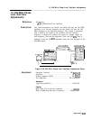
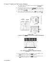
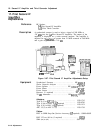
Position instrument on right side as shown in Figure 3-63, with
bottom cover removed.
Set LINE switch to ON and press QNST PRESET] on HP
8568B,
HP
8566A/B,
HP
8757A,
and HP
8340A/B.
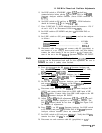
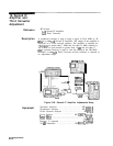
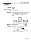
Connect 20 dB Attenuator and power splitter to RF OUTPUT
of synthesized sweeper. Connect one arm of power splitter
to R input of scalar network analyzer through Detector. See
Figure 3-63.
Set synthesized sweeper FREQUENCY MARKERS
IIv11)
to 291.4
MHz and
(M2)
to 311.4 MHz.
Press
[cwl301.4
MHz on synthesized sweeper.
Connect Power meter to other power splitter port and set
synthesized sweeper [POWER LEVEL) for Power Meter indication of
-20.0
60.1
dBm.
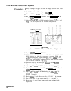
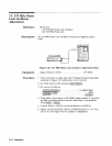
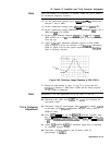
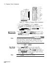
Disconnect Power Meter and connect power splitter output to
A19J1, using adapter and a BNC to SMB test cable. Refer to
Figure 3-64.
Connect A19J2 to A input of scalar network analyzer, using
adapter and another BNC to SMB test cable.
Connect synthesized sweeper SWEEP OUTPUT (rear panel),
Z-AXIS BLANK/MKRS (rear panel), and PULSE MODULATION
INPUT to proper rear-panel connectors on scalar network
Analyzer, as shown in Figure 3-63.
On the scalar network analyzer, turn Channel 2 off and press
IIVIEAS)
(A/R).
Set scalar network analyzer
[mj
to 1
dB
and set
m
(RF
LEVEL) to + 14
dB.
Set REF POSN (press REF POSN) to the fourth
division from bottom using the data knob.
On synthesized sweeper, press
[ml
(ON)
(MKR’,
and IaF].
Set [SWEEP
TIME]
to 500 ms.
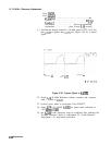
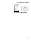
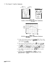
Adjust
A19
301.4 MHz
Bandpass
Filter,
A19C9
through
C12,
for
the best
bandpass
filter response with a gain of > + 14 dBm but
< + 17 dBm. See Figure 3-64 for the location of the
bandpass
adjustments.
Adjustments
3-l
13