


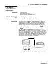
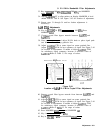

9. 3
dB
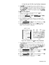
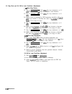
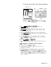
Bandwidth Adjustments
A4A9
IF CONTROL
\
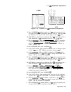
Figure 3-45. Locationof 3
dB
Bandwidth Adjustments
A4A3
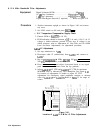
9. Press MARKER
a.
Adjust marker to 3 dB point on opposite side
of signal (CRT MKR A annotation indicates 1.00 X). There are now
two markers; one on each side of the signal at the 3
dB
points.
10. CRT MKR A annotation now indicates the 3
dB
bandwidth of the 3
MHz bandwidth. 3
dB
bandwidth should be 3.00
&to.60
MHz.
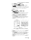
11. Key in
@YWBW)
1 MHz and [FREQUENCY SPAN] 2 MHz. If necessary,
readjust [REFERENCELEVEL) and
~CENTER
FREQUENCY), using DATA
knob to place signal peak near top of graticule and centered on
center graticule line.
12. Press MARKER [OFF), then MARKER
@].
13. Using DATA knob, adjust marker down one side of displayed signal
to the 3
dB
point; CRT MKR A annotation indicates
.707
X.
14. Adjust
A4A9R61
1 MHz for MKR A indication of 500 kHz while
maintaining marker at 3
dB
point (.707 X) using DATA knob. See
Figure 3-45 for location of adjustment.
15. Press MARKER
a.
Adjust marker to 3
dB
point on opposite side
of signal (CRT MKR A annotation indicates 1.00 X). There are now
two markers; one on each side of the signal at the 3
dB
point.
16. CRT MKR A annotation now indicates the 3
dB
bandwidth of the 1
MHz bandwidth. 3
dB
bandwidth should be 1.00
fO.10
MHz.
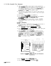
17. Key in
@G?G-BW)
300 kHz and
CFREQUENCY
SPAN) 500 kHz. If
necessary, readjust
CREFERENCE
LEVEL) and [CENTER FREQUENCY],
using DATA knob to place signal peak near top of graticule and
centered on center graticule line.
18. Press MARKER (OFF), then MARKER
@J.
19. Using DATA knob, adjust marker down one side of the displayed
signal to the 3
dB
point; CRT MKR A annotation indicates
.707
X.
20. Adjust
A4A9R62
300 kHz for MKR A indication of 150 kHz while
maintaining marker at 3
dB
point (.707 X) using DATA knob. See
Figure 3-45 for location of adjustment.
2 1. Press MARKER
[nl.
Adjust marker to 3
dB
point on opposite side
of signal (CRT MKR A annotation indicates 1.00 X).
Adjustments 3-85