


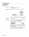

13. 20 MHz Reference Adjustments
Press &K?@
Press CnTavj:
AVmarkers
. . . . . . . . . . . . . . . . . . . . . . . . . . . . . . . . . . ..on
Vmarker 1
. . . . . . . . . . . . . . . . . . . . . . . . . . . . . . . .
800mv
Vmarker2
. . . . . . . . . . . . . . . . . . . . . . . . . . . . . . . . .
..2.7V
start marker . . . . . . . . . . . . . . . . . place at
2.7V
crossing
stop marker . . . . . . . . . . . .
. place at next
2.7V
crossing
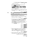
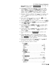
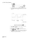
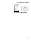
2 1. Oscilloscope display should be a 10 MHz signal of TTL level; less
than
+0.8V
to greater than
+2.7V.
See Figure 3-58 for a typical
signal.
I....
-60.000
is
40.000
“S
140.000
ns
20.0
ns/dlv
1
f800.0mV
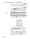
Figure 3-58. Typical Signal at
A16TP3
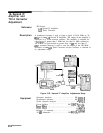
22. Install
Al6
20 MHz Reference without extenders and reconnect
cable 7 (violet) to A16J3.
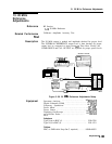
23. Connect power meter to front-panel CAL OUTPUT.
24. Adjust
A26
CAL LEVEL
A16R51
for power meter indication of
-10.0 dBm
f0.2
dB.
25. the
A23A6
Comb Generator must be readjusted after adjusting the
20 MHz Reference. Refer to Adjustments 22, Comb Generator
Adjustments, for adjustment procedure.
3-106
Adjustments