


9. 3
dB
Bandwidth
Adjustments
Reference
Related Performance
Test
Description
IF-Display Section
A4A9
IF Control
Resolution Bandwidth Accuracy Test
The CAL OUTPUT signal is connected to the RF INPUT. Each of the
adjustable resolution bandwidths is selected and adjusted for the
proper bandwidth at the 3
dB
point.
Note
Do not perform this adjustment on Option 462 instruments. Option
462 instruments require a different procedure. Adjustment 9 for
Option 462 (6
dB
or Impulse Bandwidth) is located in Chapter 4,
Option 462.
Equipment
Procedure
No test equipment is required for this adjustment.
1. Position instrument upright and remove top cover.
2. Set LINE switch to ON and press (INSTR PRESET].
3. Connect CAL OUTPUT to RF INPUT.
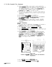
4. Key in [CENTER FREQUENCY_) 20 MHz, (FREQUENCY SPAN) 5 MHz, LIN,
and
(REs]
3 MHz.
5. Press
PREFERENCE
LEVEL] and adjust DATA knob to place signal
peak near top CRT graticule line. Signal should be centered about
the center line on the graticule. If not, press (PEAK SEARCH) and
QEXTTF).
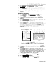
6. Press MARKER
a.
7. Using DATA knob, adjust marker down one side of the displayed
signal to the 3
dB
point; CRT MKR A annotation indicates
.707
X.
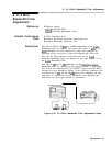
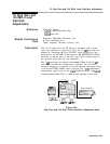
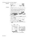
8. Adjust
A4A9R60
3 MHz for MKR A indication of 1.5 MHz while
maintaining marker at 3
dB
point (.707 X) using DATA knob. See
Figure 3-45 for location of adjustment.
3-84 Adjustments