


11. Down/Up
Converter
Adjustments
Reference
Related Performance
Test
Description
Equipment
Procedure
IF-Display Section
A4A6
Down/Up Converter
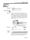
Resolution Bandwidth Switching Uncertainty Test
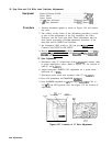
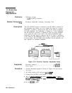
The CAL OUTPUT signal is connected to the RF INPUT connector of
the instrument and controls are set to display the signal in a narrow
bandwidth. A marker is placed at the peak of the signal to measure
the peak amplitude. The bandwidth is changed to a wide bandwidth
and the Down/Up Converter is adjusted to place the peak amplitude
of the signal the same as the level of the narrow bandwidth signal.
Optionally, the input signal is removed and the IF signal is monitored
at the output of the Bandwidth Filters using a spectrum analyzer with
an active probe. The 18.4 MHz Local Oscillator and all harmonics are
then adjusted for minimum amplitude.
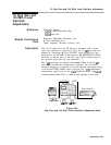
HP
85024A
HIGH FREOUENCY PROBE
PWER SUPPLY
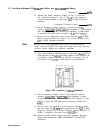
Figure 3-50. Down/Up Converter Adjustments Setup
Spectrum Analyzer
............................
HP
8566B
Active Probe
................................
HP
85024A
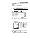
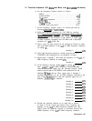
1. Position Instrument upright as shown in Figure 3-50 and remove
top cover.
2. Set LINE switch to ON and press
(JNSTR
PRESET].
3. Connect CAL OUTPUT to RF INPUT.
4. Key in [CENTER FREQUENCY) 20 MHz, (FREQUENCY SPAN) 10 kHz,
[ATTEN)
0
dB,
[REs)
1
kHz.
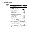
P
ress
LIN pushbutton, [PEAK SEARCH),
and then MARKER
a.
5. Key in
IJREsBW)
1 MHz.
3-92 Adjustments