


12. Time Base Adjustment (SN 2840A and Below, also 3217A05568 and Above)
14.
15.
16.
Reading 11:
mHz
Subtract the shifted frequency reading in step 11 from the
last recorded frequency in step 10. This gives the frequency
correction factor needed to adjust the
A27
10 MHz Frequency
Standard.
Frequency Correction Factor:
mHz
On the Frequency Counter, select a 1 second gate time bv
pressing,
~~~
1
@kiK].
The Frequency Counter should
now display the difference between the frequency of the INPUT
A signaland 10.0 MHz with a resolution of
0.01
Hz (10
mHz).
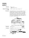
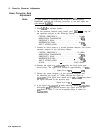
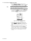
Remove the two adjustment cover screws from the
A27
10 MHz
Quartz Crystal Oscillator. See Figure 3-53 for the location of the
A27
10 MHz Frequency Standard.
Note
Do not use a metal adjustment tool to tune an oven-controlled
crystal oscillator (OCXO). The metal will conduct heat away from the
oscillator circuit, shifting the operating conditions.
17.
18.
19.
20.
Use a nonconductive adjustment tool to adjust the 18-turn FREQ
ADJ capacitor on the
A27Al
10 MHz Quartz Crystal Oscillator for
a Frequency Counter indication of 0.00 Hz. See Figure 3-53 for
the location of the A27Al 10 MHz Quartz Crystal Oscillator.
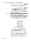
RF Section (bottom
view)
A27Al
Figure 3-53. Location of
A27Al
Adjustment
On the Frequency Counter, select a 10 second gate time by
pressing,
[GATE)
10
[GATE).
The Frequency Counter
should now display the difference between the frequency of the
INPUT A signal and 10.0 MHz with a resolution of 0.001 Hz (1
mHz).
Wait at least 2 gate periods for the Frequency Counter to settle,
and then adjust the 16-turn FINE adjustment on the
A27
10 MHz
Frequency Standard for a stable Frequency Counter indication of
(0.000 + Frequency Correction Factor)
fO.O1O
Hz.
Replace the RF Section bottom cover and reconnect the short
jumper cable between the FREQ REFERENCE INT and EXT
connectors,
3-98 Adjustments