


16. Second IF Amplifier and Third Converter Adjustment
Note
Place the Markers as accurately as possible within the cursor markers
for maximum frequency accuracy.
Note
Third Converter
Adjustment
18. On the synthesized sweeper, press
@G-X-n).
M3
-
M4
should read
between 7 and 14 MHz.
19. On the synthesized sweeper, press
[MKR]
OFF and
@iW]
OFF.
20. Set the synthesized sweeper FREQUENCY MARKERS
(M1)
to 251.4
MHz and
IIv12)
to 351.4 MHz.
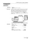
21. Set the Scalar Network Analyzer
(ml
to 10
dB
and set
IREF)
(REF LEVEL) to + 14
dB.
Set the REF POSN to one division down
from the top.
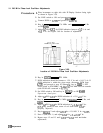
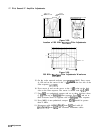
22. Adjust
A19C12
for minimum amplitude response at 258.4 MHz.
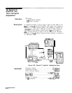
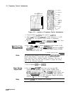
Refer to Figure 3-64 for the location of the
bandpass
adjustments.
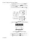
Refer to Figure 3-66 for the typical response when the
bandpass
filter is properly adjusted.
280
MHz,
Figure 3-66. Minimum Image Response at 258.4 MHz
23. Repeat the adjustments in steps 13 and 22 to assure that the
bandpass
is between 7 MHz and 14 MHz and the image response
at 258.4 MHz is minimized.
Remember to use the appropriate set up for steps 13 and 20.
24.
25.
26.
27.
28.
Disconnect the cables from
A19Jl
and
A19J2
and reconnect the
instrument cables.
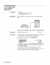
Disconnect cable 83 (gray/orange) from A20J3 and connect A20J3
to the input of HP
8566A/B
Spectrum Analyzer, using a BNC to
SMB test cable.
Press ~NSTR PRESET) on the HP
8566A/B
Spectrum Analyzer, then
key in [CENTER FREQUENCY) 280 MHz, [FREQUENCY SPAN) 2 MHz. Set
MARKER
[j),
(REFERENCE)
+ 2 dBm, and [ENTER
dB/DIv)
1
dB.
Adjust
A20
AMPTD
A20Ll
for maximum signal level as indicated
on spectrum analyzer display.
Disconnect spectrum analyzer and reconnect cable 83
(gray/orange) to A20J3.
Adjustments 3-115