


62.
63.
64.
65.
66.
67.
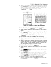
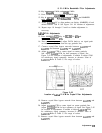
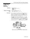
8. 21.4 MHz Bandwidth Filter Adjustments
approximately -17 kHz (to the left). If unable to achieve a “dip”
in signal amplitude, increase or decrease value of
A4ABR30.
Refer
to
‘&ble
3-3 for range of values.
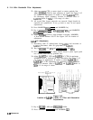
Remove short from
A4ABTP6
and short
A4ABTP3
to ground.
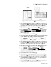
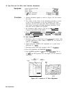
Adjust
A4ABC67
LC DIP for minimum amplitude of signal peak.
See Figure 3-43 for location of adjustment. Key in [PEAK SEARCH)
MARKER
[nl,
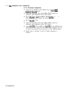
and adjust LC DIP again to offset the signal peak
approximately -17 kHz (to the left). If unable to achieve a “dip”
in signal amplitude, increase or decrease value of
A4ABR55.
Refer
to
‘Pdble
3-3 for range of values.
Set LINE switch to STANDBY.
Reinstall
A4A8
Attenuator-Bandwidth Filter without extenders.
Remove short. from
A4ABTP3.
Set LINE switch to ON. Press ~NSTR PRESET].
Go back and repeat LC adjustments for both the
A4A4
Bandwidth
filter and the
A4A8
Attenuator-Bandwidth Filter.
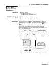
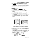
AlOdB and A20dB Adjustments
68.
69.
70.
71.
72.
73.
74.
Set, step attenuators to 25
dB.
Key in
~CENTER
FREQUENCY] 20 MHz,
~FREQUENCY
SPAN_)
3 kHz,
CATTEN]
0
dB,
[REsBWI)
1 kHz, and [REFERENCE LEVEL) -30
dBm.
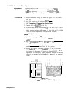
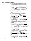
Key in LOG [ENTER
dB/DIv]
1
dB
then press MARKER (PEAK SEARCH)
MARKER
[nl
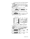
Key in [REFERENCE LEVEL) -20 dBm. Set step attenuators to 15
dB.
Adjust
A4ABR7
AlOdB to align markers on display. MARKER
A level should indicate 0.00
dB.
See Figure 3-43 for location of
adjustment.
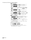
Key in (REFERENCE LEVEL) -10 dBm. Set step attenuators to 5
dB.
Adjust
A4ABR6
A2Od.B
to align markers on display. MARKER
A level should indicate 0.00
dB.
See Figure 3-43 for location of
adjustment.
Adjustments 3-83