


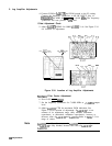
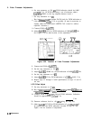
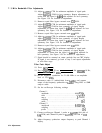

7. 3 MHz Bandwidth Filter Adjustments
10. Adjust
A4A7C15
CTR for minimum amplitude of signal peak.
Adjust
A4A7C14
SYM for best symmetry. Repeat adjustments to
ensure that the signal is
nulled
and adjusted for best symmetry.
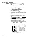
See Figure 3-38 for location of adjustments.
11. Remove crystal filter bypass network near
C23
SYM.
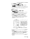
12. Adjust
A4A7C24
CTR for minimum amplitude of signal peak.
Adjust
A4A7C23
SYM for best symmetry of signal. Repeat
adjustments to ensure that signal is
nulled
and adjusted for best
symmetry. See Figure 3-38 for location of adjustments.
13. Remove crystal filter bypass network near
C32
SYM.
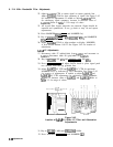
14. Adjust
A4A7C33
CTR for minimum amplitude of signal peak.
Adjust
A4A7C32
SYM for best symmetry of signal. Repeat
adjustments to ensure that signal is
nulled
and adjusted for best
symmetry. See Figure 3-38 for location of adjustments.
15. Remove crystal filter bypass network near
C41
SYM.
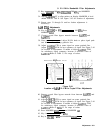
16. Adjust
A4A7C42
CTR for minimum amplitude of signal peak.
Adjust
A4A7C41
SYM for best symmetry of signal. Repeat
adjustments to ensure that the signal is
nulled
and adjusted for
best symmetry. See Figure 3-38 for location of adjustments.
17. Signal should be centered on center graticule line on CRT display.
If signal is not centered, go back to step 3 and repeat adjustments
of each filter stage.
Filter Peak Adjust
18. Press
(JNSTR
PRESET].
19. Key in
CSWEEP
TIME] 20 ms, [FREQUENCY SPAN) 0 Hz,
CREs]
10 Hz,
[REFERENCE LEVEL) -20 dBm.
20. Set the frequency synthesizer for 21.400 MHz at an amplitude
level of -25.0 dBm.
21. Disconnect cable 97 (white/violet) from
A4A8Jl
and connect
output of the frequency synthesizer to
A4A8Jl
using BNC to SMB
snap-on cable.
22. Set the oscilloscope following settings:
Channel 1
amplitude . . . . . . . . . . . . . . . . . . . . . . . . . . . . . 0.005 V/div
time . . . . . . . . . . . . . . . . . . . . . . . . . . . . . . . . . ...0.2
psldiv
mag x
. . . . . . . . . . . . . . . . . . . . . . . . . . . . . . . .
.5
(vertical)
.
coupling
. . . . . . . . . . . . . . . . . . . . . . . . . . . . . . . . . . . . . ..ac
probe . . . . . . . . . . . . . . . . . . . . . . . . . . . . . . . . . . . . . . . .
1O:l
Channel 2
amplitude
. . . . . . . . . . . . . . . . . . . . . . . . . . . . . .
O.O05V/div
coupling
. . . . . . . . . . . . . . . . . . . . . . . . . . . . . . . . . . . . . . . ac
probe
. . . . . . . . . . . . . . . . . . . . . . . . . . . . . . . . . . . . . . . .
1O:l
23. Connect oscilloscope Channel 1 probe to
A4A7TP7
(left side of
Cl4
SYM) and Channel B probe to
A4A7TP5
(left side of
C23
SYM).
24. Adjust frequency synthesizer output frequency to peak Channel 1
display.
3-74 Adjustments