


16. Second IF Amplifier and Third Converter Adjustment
17. Pilot Second IF
Amplif’ier
Adjustments
Reference
RF Section:
A9
Pilot Second IF Amplifier
A10 Pilot Third Converter
Description
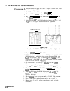
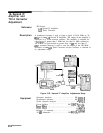
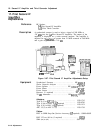
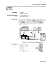
A synthesized sweeper is used to inject a signal of 269 MHz at
-20 dBm into the
A9
Pilot Second IF Amplifier. The output of the
amplifier is displayed on a scaler network analyzer. The amplifier is
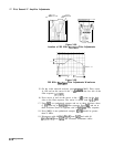
adjusted for a
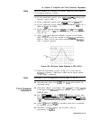
bandpass
of greater than 21 MHz centered at 269 MHz
and a gain of greater than + 10
dB.
SYNTHESIZED
!WEEPER
POAFR
METER
NETWRK ANALYZER
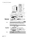
Figure 3-67. Pilot Second IF Amplifier Adjustments Setup
Equipment
Synthesized Sweeper
........................
HP
8340A/B
Scalar Network analyzer
.......................
HP
8757A
Power Splitter
...................... HP
11667A
Opt. 001
Power Meter
.................................
..HP436
A
Power Sensor
................................
..HP8482
A
Detector (2 required)
.........................
HP
11664A
20
dB
Attenuator
....................
HP
8491A,
Opt. 020
Adapters:
Type N (f) to APC-3.5 (f)
......................
1250-1745
Type N (m) to BNC (f)
(2
required)
.............
1250-0780
Type N (f) to BNC (f)
(2
required)
..............
1250-1474
APC 3.5 (f) to APC 3.5 (f)
.....................
1250-1749
Cables:
BNC to SMB Snap-On (Service Accessory) (2 required) . 85680-60093
BNC 122 cm (48 in) (3 required)
..................
10503A
SMA (m) to (m)
...............................
5061-5458
3-116 Adjustments