


7. 3 MHz
Bandwidth Filter
Adjustments
Reference
IF-Display Section
A4A7
3 MHz Bandwidth Filter
Related Performance
Resolution Bandwidth Switching Uncertainty Test
Test
Resolution Bandwidth Selectivity Test
Description
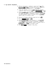
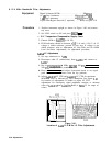
With the CAL OUTPUT signal connected to the RF INPUT, the 18.4
MHz oscillator can be adjusted with the FREQ ZERO control (on the
front panel) to peak the IF signal for maximum amplitude for the
center of the 3 MHz bandpass. Each of the five stages of the 3 MHz
Bandwidth Filter is adjusted for
bandpass
centering and symmetry.
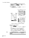
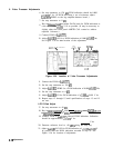
Four crystal filter bypass networks are required for alignment of the
filter stages. See Figure 3-91 for information concerning the bypass
networks.
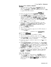
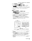
A stable 21.4 MHz signal is then applied to the IF section of the
instrument from a frequency synthesizer. Each of the first four stages
of the 3 MHz Bandwidth Filter is peaked in a 10 Hz bandwidth using
an oscilloscope display. The final stage is peaked using the spectrum
analyzer CRT display.
After all five filter stages are adjusted for centering, symmetry, and
peaking, the CAL OUTPUT signal is used to match the 10 Hz and 1
kHz bandwidth amplitudes.
SPECTRUM ANALYZER
f
3
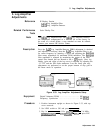
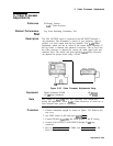
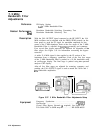
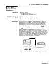
Figure 3-37. 3 MHz Bandwidth Filter Adjustments Setup
Equipment
Frequency Synthesizer
.........................
HP3335A
Oscilloscope
.................................
HP 545OlA
Crystal Filter Bypass Network
(‘t
required)
See Figure 3-91
Test Cable: BNC to SMB snap-on
.......... HP 85680-60093
3-72 Adjustments