


1. Low-Voltage Power Supply Adjustments
7. Verify that the + 120 V indicator AlA7DS2 (yellow LED) is lit.
Note
On IF-Display Sections serial prefixed
3001A
and below, indicator
AlA7DS2 is a + 100 V indicator.
8. Connect the DVM to AlA7TP3. DVM indication should be + 120.0
~k3.0
V dc. The + 120 V supply is referenced to the + 15 V supply;
therefore, if the + 120 V supply is out of tolerance, a circuit
malfunction is indicated.
Note
On IF-Display Sections serial prefixed
3001A
and below, the DVM
indication should be + 100.0
62.0
V
de.
9. Verify that the
+5.2
V indicator
AlA7DSl
(yellow LED) is lit.
10. Connect the DVM to AlA7TP2. DVM indication should be
+5.200
ho.050
V dc. The
+5.2
V supply is referenced to the + 15 V
supply; therefore, if the
+5.2
V supply is out of tolerance, a
circuit malfunction is indicated.
RF Section
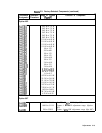
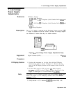
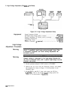
11. The
+2OV
indicator
A24DS2
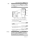
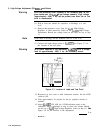
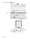
(yellow LED) should be lit. See
Figure 3-4.
A24
VOLTAGE
A24R60
REGULATOR
+2OV
ADJ
\
I
AZ4R60
+2OV
ADJ
A24
Figure 3-4. Location of RF Section Low-Voltage Adjustments
12. Connect the DVM to
A24TP3
with the ground lead to A24TPl.
Adjust
A24R60
+2OV
ADJ for a DVM indication of +20.000
&O.OlO
V dc.
13. The +
15V
indicator
A24DS4
(yellow LED) should be lit.
14. Connect the DVM to
A24TP2.
The DVM indication should be
+ 15.000
ho.050
V dc. The +
15V
supply is referenced to the
+2OV
supply, therefore, if the +
15V
supply is out of tolerance, a
circuit malfunction is indicated.
15. The +5V indicator
A24DS5
(yellow LED) should be lit.
16. Connect the DVM to
A24TP5.
The DVM indication should be
+5.230
f0.050
V dc. The +5V supply is referenced to the
+2OV
Adjustments
3-27