


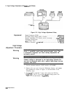
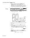

2. High-Voltage Adjustment (SN 3001A and Below)
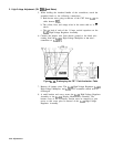
5. While holding the insulated handle of the screwdriver, touch the
grounded blade to the following connections:
a. Both brown wires going to the rear of the CRT from
AlA
via
cable harness
W21.
b. The yellow, blue, and orange wires in the same cable as “a.
”
above.
c. The top lead of each of the 11 large vertical capacitors on the
AlA
High-Voltage Regulator Assembly.
6. Connect the jumper wire from chassis ground to the black wire
coming from the
AlAll
High-Voltage Multiplier at the wire’s
connection to
AlA3Tl.
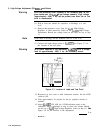
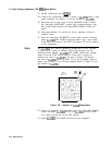
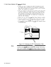
AlA
High Voltage
,T 1
AlA3Tl
AIA3
Figure
3-l
1.
Discharging the CRT Post-Accelerator Cable
7. Remove all jumper wires. The
AlA
High-Voltage Regulator,
AlAll
High-Voltage Multiplier, and
AlVl
CRT assemblies should now be
discharged.
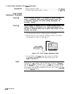
8. A small bracket and screw secure the
AlA
High-Voltage Regulator
Assembly to the
AlAlO
Display Motherboard Assembly. The
bottom cover of the IF-Display Section must be removed to gain
access to this screw prior to removal of the
AlA
High-Voltage
Regulator Assembly.
3-38 Adjustments