


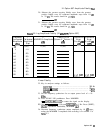

9. Impulse Bandwidth Adjustments
[REFERENCE LEVEL] and using the DATA knob to place the signal
peak near the top of the graticule.
24. Press MARKER
IOFF),
then MARKER (al.
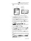
25. Using the DATA knob, adjust the marker down one side of
the displayed signal to the 7.3
dB
point; CRT MKR annotation
indicates 0.430 X.
26. Adjust
A4A9R65
10 kHz for MKR A indication of 5.00 kHz while
maintaining the marker at 0.430 X using the DATA knob. Refer to
Figure 4-8 for the adjustment location.
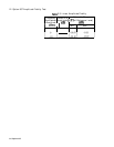
27. Press MARKER
Ia].
Adjust the marker to the 7.3
dB
point on the
opposite side of the signal (CRT MKR A annotation indicates 1.00
Xl*
28. The CRT MKR A annotation now indicates the impulse bandwidth
of the 10 kHz bandwidth. The impulse bandwidth should be 10.0
fl.O kHz
29. Key in
@E’GZT]
3 kHz, [FREQUENCY SPAN] 5 kHz, [PEAK SEARCH), and
@iiGGZQ.
If necessary, readjust by pressing [REFERENCE LEVEL)
and using the DATA knob to place the signal peak near the top of
the graticule.
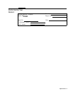
30. Press MARKER
a
and MARKER
a.
31. Using the DATA knob, adjust the marker down one side of the
displayed signal to the 7.3
dB
point; CRT MKR A annotation
indicates 0.430 X.
32. Adjust
A4A9R66
3 kHz for MKR A indication of 1.5 kHz while
maintaining the marker at 0.430 X using the DATA knob. Refer to
Figure 4-8 for the adjustment location.
33. Press MARKER In]. Adjust the marker to the 7.3 dB point on the
opposite side of the signal (CRT MKR A annotation indicates 1.00
Xl.
34. The CRT MKR
@
annotation now indicates the impulse
bandwidth of the 3 kHz bandwidth. The impulse bandwidth
should be 3.00
ho.30
kHz
Option 462 4-29