


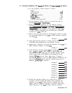

11. Down/Up Converter Adjustments
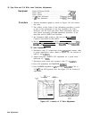
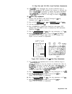
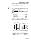
6. Adjust A4A6AlR29 WIDE GAIN to align markers on CRT display.
MKR A level should indicate 1.00 X. See Figure 3-51 for location of
adjustment.
7. Disconnect CAL OUTPUT from RF INPUT.
Optional
Note
Perform the following procedure if the A4A6Al assembly is replaced
or the A4A6Al 21.4 MHz
Bandpass
Amplifier Filter is worked on.
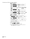
1. Disconnect CAL OUTPUT from RF INPUT.
2. Key in [REFERENCE LEVEL) -70 dBm,
[REs]
1 kHz, and MARKER
IOFF).
3. Set the second spectrum analyzer’s to the following settings:
RESOLUTION BANDWIDTH
. . . . . . . . . . . . . . . . . . 100
kHz
FREQUENCY SPAN
. . . . . . . . . . . . . . . . . . . . . . . . . . . 10 MHz
CENTER FREQUENCY
. . . . . . . . . . . . . . . . . . . . . . 18.4 MHz
RF ATTENUATION
. . . . . . . . . . . . . . . . . . . . . . . . . . . . . . 10 dB
REFERENCE LEVEL . . . . . . . . . . . . . . . . . . . . . . . . . . . 0 dBm
SCALE . . . . . . . . . . . . . . . . . . . . . . . . . . . . . . . . LOG 10
dB/div
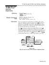
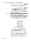
4. Connect the second spectrum analyzer to
A4A4TP7
using and
active probe. See Figure
3-50
for test setup.
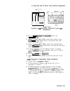
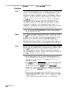
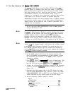
5. Adjust A4A6AlC31 18.4 MHz NULL to null the 18.4 MHz Local
Oscillator signal and all displayed harmonics. See Figure 3-51 for
location of adjustment.
A4A6
DOWN/UP CONVERTER
\
R2’
1.
,
18
4
,“,‘;
NIJLL
WIDE,<
r
2
:AlN
AZR33
Figure 3-51. Location of Down/Up Converter Adjustments
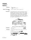
6. 18.4 MHz signal and displayed harmonics should be below -10
dBm (-30 dBm on display due to
1O:l
divider). If unable to adjust
A4A6AlC31 18.4 MHz NULL for proper indication, increase value
of
A4A5RlO.
See Figure 3-49 for the location of
A4A5RlO.
Refer
to
‘Iable
3-3 for range of values.
Adjustments 3-93