


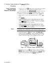

3. Preliminary Display Adjustments (SN 3004A and Above)
AlA
A3A2
A3Al
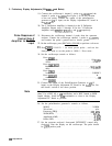
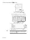
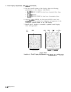
Figure 3-24. Location of
AlA
and A3A2
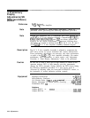
TP5Ol
R127
P120
Cl09
TP105
R227
c204
R220
R217
J5
GEID
c307
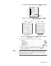
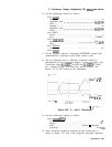
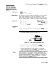
Figure 3-25.
AlA
Adjustment Locations
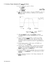
10. Set the Pulse/Function Generator controls as follows:
MODE . . . . . . . . . . . . . . . . . . . . . . . . . . . . . . . . . . . . . . . . . . . NORM
Waveform
. . . . . . . . . . . . . . . . . . . . . . . . . . . . . . . . . . . . . . . . . . . . . . . . .
..pulse
Frequency (FRQ) . . . . . . . . . . . . . . . . . . . . . . . . . . . . . . . . ,200 kHz
Width(WID)
. . . . . . . . . . . . . . . . . . . . . . . . . . . . . . . . . . . . . . . . . . . . ...250 ns
Amplitude (AMP) . . . . . . . . . . . . . . . . . . . . . . . . . . . . . . . . .
.2.00
V
Offset (OFS) . . . . . . . . . . . . . . . . . . . . . . . . . . . . . . . . . . . .O.OOO
mV
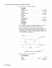
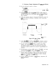
11. Connect the output of the Pulse/Function Generator to
Jl
(X
input) on the Display Adjustment PC board in the
A3A2
slot as
shown in Figure 3-23.
Note
The pulse/function generator’s output must be terminated with 50
ohms. Use a BNC tee, a
5Ofl
termination, and a BNC female to SMB
female adapter. Install the
5052
termination as close to the Display
Adjustment PC Board as possible.
3-54 Adjustments