


6. Resolution
Bandwidth
Switching
Uncertainty Test
Related Adjustments
Specification
Description
Equipment
Procedure
(For instruments with Option 462, refer to Chapter 4.)
3 MHz Bandwidth Filter Adjustments
21.4 MHz Bandwidth Filter Adjustments Down/Up Converter
Adjustments
(uncorrected; referenced to 1 MHz bandwidth; 20
-
30°C
after 1 hour
warm-up)
k2.0
dB,
10 Hz bandwidth
f0.8
dB,
30 Hz bandwidth
*0.5
dB,
100 Hz to 1 MHz bandwidth
fl.O
dB,
3 MHz bandwidth 30 kHz and 100 kHz bandwidth switching
uncertainty figures only applicable 190% Relative Humidity
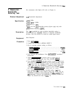
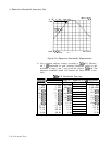
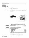
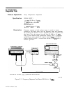
The CAL OUTPUT signal is applied to the input of the spectrum
analyzer. The deviation in peak amplitude of the signal trace is then
measured as each resolution bandwidth filter is switched in.
None Required
1.
Press (INSTR PRESET).
2.
Connect CAL OUTPUT to SIGNAL INPUT 2.
3.
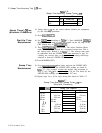
Key in the following control settings:
(CENTER FREQUENCY)
[FREQUENCY SPAN]
REFERENCE LEVEL]
&sTE,
..................
......................
20
..................
.......................
5
..................
......................
-8
..................
.......................
1
4.
Press LOG (ENTER
dB/bIvj
and key in 1
dB.
Press MARKER
[PEAK SEARCH)
a.
5.
6.
Press
m,@J
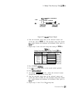
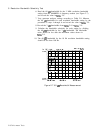
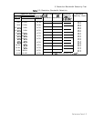
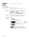
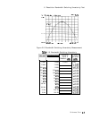
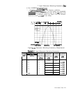
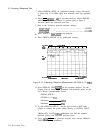
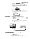
Key in settings according to Table 2-10. Press MARKER
[PEAK SEARCH] at each setting, then read the amplitude deviation
from the MARKER A readout at the upper right of the display (see
Figure 2-8). The allowable deviation for each resolution bandwidth
setting is shown in the table.
MHz
MHz
dBm
MHz
2-18 Performance Tests