


Crystal Filter Bypass Network Configuration
Crystal Filter
Bypass Network
Configuration
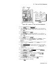
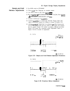
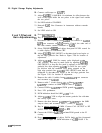
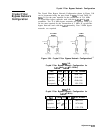
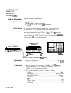
The Crystal Filter Bypass Network Configuration shown in Figure 3-94
can be constructed using the parts listed in
Iable
3-8 and Table 3-9.
Table
3-8 list the parts required for the construction of 21.4 MHz
IF crystal-filter bypass networks used with the
A4A4
and
A4A8
assemblies. Two 21.4 MHz bypass networks are required. Table 3-9
list the parts required for the construction of 3 MHz IF crystal-filter
bypass networks used with the
A4A7
assembly. Four 3 MHz bypass
networks are required.
21.4 MHz 3 MHz
BYPASS
BYPASS
CAPACITOR
1
oop,
CAPACITOR
047
“i
Figure 3-94. Crystal Filter Bypass Network Configurations
lhble
3-8.
Crystal Filter Bypass Network Configuration for
A4A4
and
A4A8
(21.4 MHz)
Part
Value Qty. CD HP Part Number
Resistor 31.662 2
2
0698-7200
Capacitor 100 pF 2
9
0160-4801
Capacitor 910 pF 2
9
0160-6146
Receptacle
-
4
1
1251-3720
lhble
3-9.
Crystal Filter Bypass Network Configuration for
A4A7
(3 MHz)
1
Fart
1
Value
1
Qty.
1
CD
1
HP
Part Number I
Resistor 2.70
4
4
0683-0275
Capacitor 0.047 PF
4
9
0170-0040
Receptacle
-
8
1
1251-3720
Adjustments
3-151