


25. Digital Storage Display Adjustments
Sample and Hold
13. Set LINE switch to STANDBY.
Balance Adjustments
14. Place
A3A3
Line Generator on extender boards.
15. Set LINE switch to ON. Press
QNSTR
PRESET].
16. Key in
C-1
0
’
(RECORDER LOWER LEFT) 0 [Hz). Press
[SHIFT]
0
1
(RECORDER UPPER RIGHT) 1028
a.
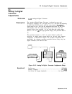
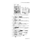
17. Connect oscilloscope to
A3A3TP4.
18. Connect
A3A3TPll
to oscilloscope External Trigger Input and
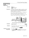
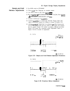
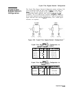
adjust oscilloscope controls for display as shown in Figure 3-91.
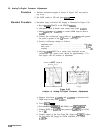
19. Adjust
A3A2R50
X S&H BAL for minimum
de
offset between the
level of the signal inside the two pulses to the signal level outside
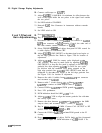
the two pulses. Figure 3-91 shows a properly adjusted waveform.
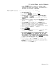
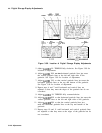
Figure 3-92 shows the waveform before adjustment. Refer to
Figure 3-90 for location of adjustment.
1
50.0
rnV/dlV
ioffset:
0.000 V
:
10.00
:
I
dC
-2:‘9000d
us
~4*..,..600
..ns
2.10000
us
500
ns/div
4
f300.5rnV
Figure 3-91. Sample and Hold Balance Adjustment Waveforms
1
50.0
mV/dlv
#offset:
0.000 v
i
10.00
:
1 dc
;
.A.
,, .
.
.
.
.
./
..i
..:.
i..
:...;..
/
.
./
i
‘
.+
.:.
.+
:
i
,,
..i
,,,,,,,,
.,,,
.,
-2.90000
us
-400.000
ns
2.10000
us
500
ns/dlv
4
f300.5BV
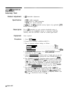
Figure 3-92. Waveform Before Adjustment
Adjustments
3-147