


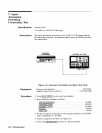
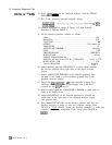

8. Frequency Response Test
100Hzto
100
kHz
32.
33.
34.
35.
36.
37.
38.
39.
40.
41.
Press (INSTR PRESET) on the spectrum analyzer. Activate SIGNAL
INPUT 1.
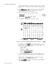
Key in the following spectrum analyzer settings:
START FREQ) . . . .
.._..............................
;&TEq
. . . . . . . . . . . . . . . . . . . . . . . . . . . . . . . . . . . . . . . .
...........
1
kHz
.........
100
kHz
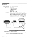
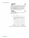
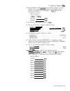
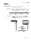
Connect equipment as shown in Figure 2-15 with function
generator to SIGNAL INPUT 1.
Set the function generator controls as follows:
LINE . . . . . . . . . . . . . . . . . . .. . . . . . .. . . . . . . . . . . . . . . . . . . . ON
RANGE Hz . . . . . . . . . . . . . . . . . . . . . . . . . . . . . . . . . . . . . . . . . . 10 K
FUNCTION . . . . . . . . . . . . . . . . . . . . . . . . . . . . . . . . . . . . . . . . . . . . .
-
OFFSET . . . . . . . . . . . . . . . . . . . . . . . . . . . . . . . . . . . . . CAL (button in)
AMPLITUDE . . . . . . . . . . . . . . . . . . . . . . . . . . . . . . . . . . . . . . . . . . . 1 V
AMPLITUDE VERNIER . . . . . . . . . . . . . . . . . . . . . . . . . . . . . . midrange
SYM . . . . . . . . . . . . . . . . . . . . . . . . . . . . . . . . . . . . . . . . . . . . . . . . . CAL
TRIGGER PHASE . . . . . . . . . . . . . . . . . . . . . . . . . . . . . . . . FREE RUN
MODULATION
. . . . . . . . . . . . . . . . . . . . . . . . . . . . . . . . . . . . . . . all out
MODULATION RANGE Hz . . . . . . . . . . . . . . . . . . . . . . . . . . . . . . . . I
MODULATION RANGE Hz VERNIER .......fully CCW
MODULATION SYM
. . . . . . . . . . . . . . . . . . . . . . . . . . . . . . . . . . . . CAL
Percent Modulation
. . . . . . . . . . . . . . . . . . . . . . . . . . . . . . . . . . .
.. . . fully
CW
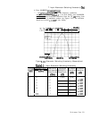
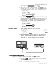
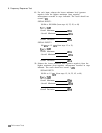
Adjust function generator FREQUENCY to place signal between
the last two graticule lines (right side) on the signal analyzer
display.
Adjust AMPLITUDE VERNIER on the function generator until
the peak of the signal is at the reference graticule line on the
spectrum analyzer display.
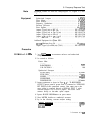
Press LOG
CENTER
dB/DIv_) 1
dB
on the spectrum analyzer. Press
DISPLAY LINE
[ENTER]
and set the Display Line to the level
recorded for 100 kHz in step 25.
Adjust function generator AMPLITUDE VERNIER to place peak of
signal at the Display Line.
Adjust FREQUENCY on the function generator to position the
signal trace at the right edge of the spectrum analyzer display
(last graticule line).
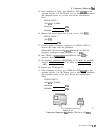
Press MODULATION SWP on the function generator and allow the
function generator to make at least two complete sweeps. Press
TRACE A [MAX HOLD). Allow the function generator to make one
complete sweep. After completion of the sweep, press TRACE A
m).
2.28
Performance Tests