


2. High-Voltage Adjustment (SN 3001A and Below)
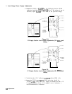
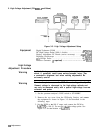
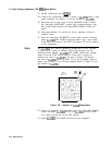
DIGITIZING
OSCILLOSCOPE
HI-VOLTAGE
SIGNAL ANALYZER
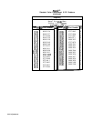
Figure 3-5. High Voltage Adjustment Setup
Equipment
Digital Voltmeter (DVM)
...................................
.HP
3456A
DC High-Voltage Probe (1000: 1 divider)
..................
HP
34111A
Display Adjustment PC Board (service accessory)
......
.85662-60088
Digitizing Oscilloscope
....................................
HP
54501A
1O:l
Divider Probe
........................................
HP
10432A
Function Generator
(2
required)
...........................
HP
3312A
High-Voltage
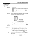
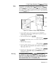
Adjustment Procedure
Warning
In the following procedure, it is necessary to probe voltages
which, if contacted, could cause serious personal injury. Use
a nonmetallic alignment tool when making adjustments. Be
extremely careful.
Warning
Do not attempt to measure the CRT filament voltage directly. The
filament voltage is referenced to the high-voltage cathode and
can only be measured safely with a special high-voltage true-rms
voltmeter and probe.
1. Set the spectrum analyzer’s LINE switch to STANDBY.
2. Remove the top cover from the IF-Display Section, and connect
the equipment as shown in Figure 3-5 and described in the
following steps.
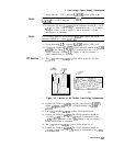
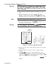
3. Set the DVM to the 100 V range, and connect the DVM to
AlA7TP3
(+ 100 V). Do not use the high-voltage probe. See
Figure 3-6 for the location of
AlA7TP3.
3.30
Adjustments