


3. Preliminary Display Adjustments (SN 3001A and Below)
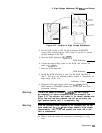
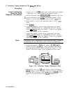
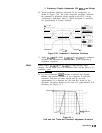
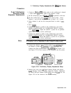
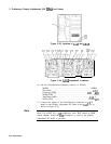
16. Three waveforms should be displayed on the oscilloscope, as
shown in Figure 3-20. The lower composite waveform represents
the combined X deflection voltage applied to the CRT. Use the
oscilloscope’s front-panel knob to adjust waveform fl sensitivity
for approximately 8 vertical divisions.
hp
stopped
remote listen
:
DISPLAY
-125.000 “s
125.000
ns
375.000
“S’
50.0
ns/div
Figure 3-20. Composite X Deflection Waveform
17. Adjust AlA4R28 HF GAIN,
AlA4Cl0,
and
AlA4Cll
for minimum
overshoot and minimum rise and fall times of the composite X
deflection waveform.
Note
Always adjust
AlA4ClO
and
AlA4Cll
in approximately equal
amounts. Do not adjust one to its minimum value and the other to its
maximum value.
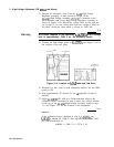
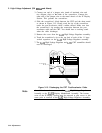
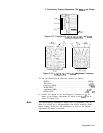
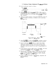
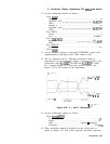
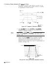
18. Use the oscilloscope
Intnv)
markers to measure the risetime,
falltime, and percent overshoot of the composite X defection
waveform. Rise and fall times should both be less than
approximately 65 ns between the 10% and 90% points on the
waveform. Overshoot should be less than 3% (approximately 0.25
divisions). See Figure 3-2 1.
OVERSHOOT
OVERSHOOT
Figure 3-2 1.
Rise and Fall Times and Overshoot Adjustment Waveform
Adjustments
3-49