


3. Preliminary Display Adjustments (SN 3004A and Above)
Procedure
X and Y Deflection
1. Connect a
1O:l
(10
MQ)
divider probe to the oscilloscope’s channel
Amplifier Pulse
1 input and a
1O:l
divider probe to the channel 4 input.
Response Adjustments
2. On the oscilloscope, press (RECALL)
(CLEARI)
to perform a soft reset.
3.
On the oscilloscope, press
(CHAN)
more preset probe , select
channel 1, and use the front-panel knob to select a 10: 1 probe.
4. Select channel 4, and use the front-panel knob to select a
IO:1
probe.
5. Press
ml.
6. Connect the channel 1 probe to the oscilloscope’s rear panel
PROBE COMPENSATION AC CALIBRATOR OUTPUT connector.
Press
CAUTO-
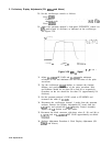
SCALE). Adjust the channel 1 probe for an optimum
square wave display on the oscilloscope.
7. Connect the channel 4 probe to the oscilloscope’s rear panel
PROBE COMPENSATION AC CALIBRATOR OUTPUT connector.
Press [AUTO- SCALE]. Adjust the channel 4 probe for an optimum
square wave display on the oscilloscope.
Note
Each probe is now compensated for the oscilloscope input to which it
is connected. Do not interchange probes without recompensating.
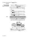
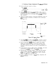
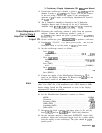
8. Connect the channel 1
IO:1
divider probe to AlA2TP204, and
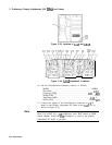
the channel 4 probe to AlA2TP205, as shown in Figure 3-23.
Connect the probe ground leads to AlA2TP106. See Figure 3-24
and Figure 3-25 for the location of the assemblies and test points.
5On
TERkllNATlON
W
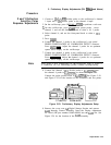
Figure 3-23. Preliminary Display Adjustments Setup
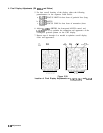
9. Remove the cover over
A3
Digital Storage Section and remove
A3A2
Intensity Control Assembly. Insert the Display Adjustment
PC board (HP part number 85662-60088) into the
A3A2
slot. See
Figure 3-24 for the location of the
A3A2
assembly.
Adjustments 3-53