


19. Second Converter Adjustments
Second Converter
53. Repeat steps 14 through 19 to ensure that Second LO frequency
Final Adjustments
and shift are still properly adjusted.
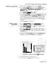
54. Check the
bandpass
at the 3
dB
points for both the
2ND
LO
T
and
1.
On the scalar network analyzer, press [%i?%@ Max. Press
cursor A
a
and set the cursor at the -3
dB
point
50.1
dB.
Press
cursor A, cursor A, and set the cursor to the corresponding -3
dB
point on the opposite side of the signal. The cursor should now
read 0
kO.1
dB.
55. On the synthesized sweeper, press
Ihns)
and place the marker on
either cursor A. Press
(M4),
and place the marker on the cursor A
on the opposite side of the trace.
56. On the synthesized sweeper, press
[MKRn),
and read the
bandpass
(M3
-
M4)
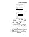
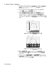
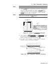
shown on the ENTRY DISPLAY. Press
C-1
OFF. See
Figure 3-74 and Figure 3-75.
57. Disconnect all test equipment from HP
8568B
Spectrum Analyzer
and reconnect all cables within the instrument: cable 80
(gray/black) between A23A3J6 and A9J1, and cable 92 (white/red)
between A23A3J5 and
A19Jl.
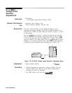
58. Connect HP
8568B
Spectrum Analyzer CAL OUTPUT to SIGNAL
INPUT 2. Key in (CENTER FREQUENCY) 20 MHz, (FREQUENCY SPAN) 1
MHz, (REFERENCE LEVEL] -7 dBm, SCALE LOG [ENTER
dB/DIv)
1
dB,
(REs)
300
kHz.
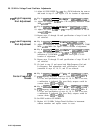
59. Key in
@iFi]
@j
u
, (PEAK SEARCH] Key in
m
@
T
and note
signal amplitude as indicated by marker level CRT annotation.
60. Continue to key in
ISHIFT)
@)
u then (SHIFT)
(IJ
T
while adjusting
A23A3Z4
for maximum amplitude and the same amplitude in both
states of the Second LO
3x0.1
dB.
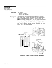
61. Reinstall RF Converter in instrument. See installation procedure
in RF Section of Troubleshooting and Repair Manual, Volume 1.
Adjustments 3-129