


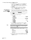

3. Preliminary Display Adjustments (SN 3001A and Below)
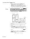
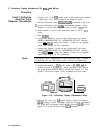
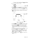
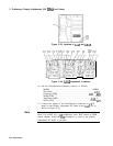
19. Connect the oscilloscope’s channel 1 probe to
AlA5El
and the
channel 4 probe to
AlA5E2.
See Figure 3-18 for the location
of the test points. Connect the output of the pulse/function
generator to
52
(Y input) on the Display Adjustment PC board in
the
A3A2
slot.
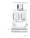
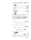
20. The Y Deflection Amplifier is identical to the X Deflection
Amplifier. Repeat steps 12 through 18 for the Y Deflection
Amplifier using
R7,
R27,
R28,
ClO,
and Cl1 respectively.
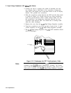
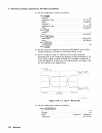
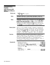
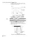
Pulse Response of
21. Disconnect the oscilloscope channel 4 probe from the spectrum
Control Gate Z
analyzer. Connect the oscilloscope channel 1 probe to AlA2TP2,
Amplifier to BLANK
and connect the probe’s ground lead to chassis ground.
Input
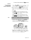
22. On the oscilloscope, press [RECALL) (CLEAR) to perform a soft reset.
2%
Press
(TiTiiQ
CHANNEL 1
on,
more preset probe , and use the
front-panel knob to set the probe to 10.00: 1. Press more .
24. Set the oscilloscope controls as follows:
Press
(CHAN):
amplitude scale . . . . . . . . . . . . . . . . . . . . . . . . . . . . . . . . . 10.0 V/div
offset
. . . . . . . . . . . . . . . . . . . . . . . . . . . . . . . . . . . . . . . . . . . . . ...25.0000 V
Press
[TlMEBASEI):
time scale . . . . . . . . . . . . . . . . . . . . . . . . . . . . . . . . . . . . . . . . .
..50.0ns/div
delay . . . . . . . . . . . . . . . . . . . . . . . . . . . . . . . . . . . . . . . . . . 125.000 ns
Press
ITRIG]:
level. . . . . . . . . . . . . . . . . . . . . . . . . . . . . . . . . . . . . . . . . 5.00000 V
c
Press
(-1:
connect dots . . . . . . . . . . . . . . . . . . . . . . . . . . . . . . . . . . . . . . . . . . . . . . .
..on
Press
@ii??@.
25. Connect the output of the Pulse/Function Generator to
53
(Z
input) on the Display Adjustment PC Board in the
A3A2
slot. Set
the board’s switch to the down position.
Note
The pulse/function generator’s output must be terminated with 50
ohms. Use a BNC tee, a
5062
termination, and a BNC female to SMB
female adapter. Install the 500 termination as close to the Display
Adjustment PC Board as possible.
26. Set the pulse/function generator’s controls as follows:
MODE . . . . . . . . . . . . . . . . . . . . . . . . . . . . . . . . . . . . . . . . . . NORM
Waveform
. . . . . . . . . . . . . . . . . . . . . . . . . . . . . . . . . . . . . . . . . . . . . . . . . ..pulse
Frequency (FRQ) . . . . . . . . . . . . . . . . . . . . . . . . . . . . . . . . . ,200 kHz
Width(WID)
. . . . . . . . . . . . . . . . . . . . . . . . . . . . . . . . . . . . . . . . . . . . .
..250ns
Amplitude (AMP) . . . . . . . . . . . . . . . . . . . . . . . . . . . . . . . . . . .
.4.OOV
Offset (OFS) . . . . . . . . . . . . . . . . . . . . . . . . . . . . . . . . . . . . . . . .
.2.OOV
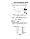
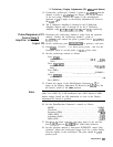
27. Set the spectrum analyzer’s front-panel INTENSITY control fully
clockwise. Note the display on the oscilloscope. The pulse should
be >55V peak-to-peak.
3-50 Adjustments