


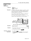

25. Digital Storage Display Adjustments
20.
21.
22.
23.
24.
Set LINE switch to ON.
X and Y Offset and
25.
Gain Adjustments
26,
27.
Press (INSTR PRESET).
Key in [FREQUENCY SPAN] 0 Hz, [SWEEP TIME) 100
ps.
Disconnect cable 9 (white) from A3A9J2 and connect to A3A2J2
LG/FS
test connector on
A3A2
Intensity Control; the other end of
the cable remains connect connected to A3A2J1.
28.
29.
30.
31.
32.
33.
34.
35.
36.
37.
38.
39.
40.
Connect oscilloscope to
A3A3TP7.
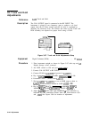
Adjust
A3A2R51
Y S&H BAL for minimum dc offset between the
level of the signal inside the two pulses to the signal level outside
the two pulses.
Set LINE switch to STANDBY.
Reinstall
A3A3
Line Generator in instrument without extender
boards.
Select TRIGGER
[VIDEO]
and adjust front-panel LEVEL control for
a stable display on instrument CRT.
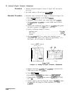
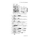
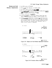
Adjust
A3AlR34 SWP OFFSET so that the signal trace begins at
the left edge graticule line. Refer to Figure 3-90 for location of
adjustment.
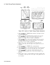
Adjust
A3A3R4
X GAIN for twenty cycles displayed on the
CRT graticule. This may be made easier by adjusting A3AlR34
SWP OFFSET so that the first peak is centered on the left edge
graticule line, then adjusting
A3A3R4
X GAIN for two cycles
per division with the twentieth cycle being centered on the
right edge graticule line.
A3AlR34 SWP OFFSET must then be
readjusted so that the trace begins at the left edge graticule line.
See Figure 3-90. for location of adjustment.
Remove the cable 9 (white) from A3A2J2
LG/FS
test connector
and reconnect to A3A9J2.
Remove cable 7 (violet) from
A4AlJl.
Short A3A9TPl to
A3A9TP3
or connect an SMB snap-on short to
A3A9Jl.
Connect DVM to A3A9TP3 and DVM ground to
A3A9TPl.
Press LIN pushbutton.
DVM indication should be 0.000
kO.002
V dc.
Adjust
A3A3R43
YOS to align the bottom graticule line with the
fast sweep signal trace.
Remove the short between
A3A9TPl and A3A9TP3 (or the SMB
snap-on short) and reconnect cable 7 (violet) to
A4AlJl.
Key in [CENTER FREQUENCY) 20 MHz. Connect CAL OUTPUT to RF
INPUT. Press LOG
(ENTER
dB/DIv]
10
dB.
Connect the DVM to
A4AlTP3
and the DVM ground to the IF
casting.
Press
[REFERENCE LEVEL) and adjust DATA knob and the frontpanel
AMPTD CAL adjust for DVM indication of
+2.000
50.002 V dc.
3-148
Adjustments