


8. Frequency
Response Test
Related Adjustment
Specification
Description
SYNTHESIZED SWEEPER
Slope Compensation Adjustment
SIGNAL INPUT 1
~tl.5
dB,
100 Hz to 1.5
GHz
*I
dB,
100 Hz to 500 MHz
SIGNAL INPUT 2
fl
dB,
100 kHz to 1.5
GHz
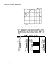
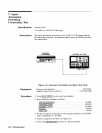
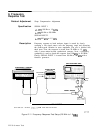
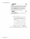
Frequency response at both analyzer inputs is tested by slowly
sweeping a flat signal source over the frequency range and observing
the peak-to-peak variation in trace amplitude. The test is divided into
three parts. First, the response is tested from 20 MHz to 1.5
GHz
with a power-meter-leveled synthesized sweeper. Next, a frequency
synthesizer is used to check the response from 100 kHz to 20 MHz.
Finally, SIGNAL INPUT 1 is tested from 100 Hz to 100 kHz with a
function generator.
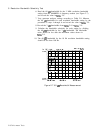
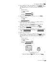
RECORDER
OUTPUT
POWER METER
SPECTRUM ANALYZER
I
GNAL
NPUT
.\
I
ADA,PT,ERS
I
I
I I
\I
POWER SENSOR
OPTION 001. ADD 50
OHMS/75
OHM PAD AND ADAPTER
gb12b
Figure 2-11. Frequency Response Test Setup (20 MHz to 1.5
GHz)
2-22 Performance Tests