


11. Down/Up Converter Adjustments
Down Converter Gain
Adjustment
Note
If a gain problem is suspected in the 10 Hz to 1 kHz resolution
bandwidths, perform the following procedure to test and adjust the
gain through
A4A6A2.
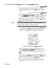
1. Place
A4A6
on extender boards.
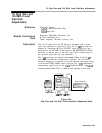
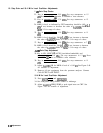
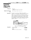
2. On the spectrum analyzer being tested, press QNST PRESET], and set
the spectrum analyzer to the following settings:
CENTER FREQUENCY . . . . . . . . . . . . . . . . . . . . . . . . 20 MHz
RESOLUTION BANDWIDTH
. . . . . . . . . . . . . . . . . . . . . 1
kHz
FREQUENCY SPAN . . . . . . . . . . . . . . . . . . . . . . . . . . . . . . 0 Hz
REFERENCE LEVEL . . . . . . . . . . . . . . . . . . . . . . . . -10 dBm
INPUT ATTENUATION . . . . . . . . . . . . . . . . . . . . . . . . . . 10 dB
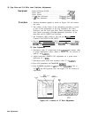
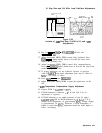
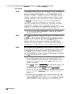
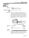
3. Connect an active probe to a second spectrum analyzer, and set the
spectrum analyzer to the following settings:
CENTER FREQUENCY . . . . . . . . . . . . . . . . . . . . . . 21.4 MHz
RESOLUTION BANDWIDTH
. . . . . . . . . . . . . . . . . . 100
kHz
FREQUENCY SPAN . . . . . . . . . . . . . . . . . . . . . . . . . .
..200
Hz
REFERENCE LEVEL . . . . . . . . . . . . . . . . . . . .
_
. . . -30 dBm
INPUT ATTENUATION . . . . . . . . . . . . . . . . . . . . . . . . . . 10 dB
SCALE
. . . . . . . . . . . . . . . . .
_
. . . . . . . . . . . . . . . LOG 1 dB/div
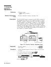
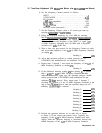
4. Measure the signal at A4A6A2TP4 using the active probe and
record below. The signal level should be approximately -33 dBm.
Signal level at
TP4
dBM
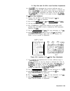
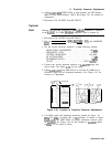
5. Change the center frequency of the spectrum analyzer used
for measuring the signals to 3 MHz. Measure the signal at
A4A6A2Pl-9. The signal level should be 10
dB
f0.6
dB
lower than
the signal measured in the previous step.
Signal level at
Pl-9
dBM
6. If the signal at A4A6A2Pl-9 needs adjusting, change
A4A6A2R33.
(Decreasing
R33
ten percent increases the signal level by 0.6
dB.)
Refer to Table 3-3 for the acceptable range of values for
A4A6A2R33.
3-94 Adjustments