


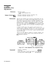
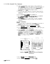

8. 21.4 MHz Bandwidth Filter Adjustments
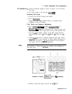
22. Adjust
A4A4C73
CTR to center signal on center graticule line.
Adjust
A4A4C65
SYM for best symmetry of signal. See Figure 3-42
for location of adjustments. If unable to adjust
A4A4C65
SYM
for satisfactory signal symmetry, increase or decrease value of
A4A4C66.
Refer to
Table
3-3 for range of values.
23. All crystal filter bypass networks are removed. Signal should be
centered and symmetrical. If not, go back to step 16 and repeat
adjustments.
24. Press MARKER
SPEAK
SEARCH] and MARKER In].
25. Key in
~FREQUENCY
SPAN] 20 kHz,
[REs]
3
kHz,
and MARKER
[PEAK SEARCH].
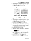
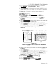
26. Adjust
A4A4R49
XTAL to align markers on display. MARKER
A level should indicate 1.00 X. See Figure 3-42 for location of
adjustment.
A4A8
LC Adjustments
27. Disconnect cable 97 (white/violet) from
A4A6Jl
and reconnect to
A4A8Jl.
Reconnect cable 89 (gray/white) to
A4A6Jl.
28. Key in
[-BW)
100 kHz and [FREQUENCY SPAN] 200 kHz.
29. Press [REFERENCE LEVEL) and adjust DATA knob to place signal peak
two division from the top graticule line.
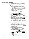
30. Adjust A4AW32 LC CTR and
A4A8C46
LC CTR for maximum
MARKER level as indicated by CRT annotation. See Figure 3-43
for location of adjustments. If unable to adjust
A4A8C32
and
A4AW46 LC CTR adjustments for satisfactory signal amplitude,
increase or decrease value of A4AW35 and
A4A8C49.
Refer to
‘Iable
3-3 for range of values.
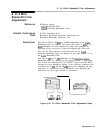
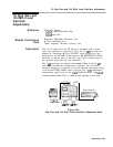
A4A8
Attenuator
BandwIdth
Filter
A4A8
Figure 3-43.
Location of
A4A8
21.4 MHz LC Filter and Attenuation
Adjustments
31. Key in
[REsj
1 MHz and @@?ZGGi] 1 MHz.
32. Press MARKER (PEAK SEARCH] and MARKER
@.
3-80
Adjustments