


23. Analog-To-Digital Converter Adjustments
Procedure
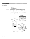
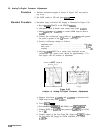
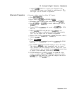
1. Position instrument upright as shown in Figure 3-85 and remove
top cover.
2. Set LINE switch to ON and press
~NSTR PRESET).
Standard Procedure
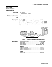
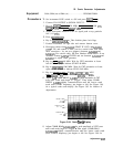
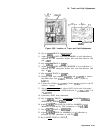
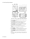
3. Procedure using Low-Noise DC Supply is illustrated in Figure 3-93.
a. Key in
[BLANK)
TRACE A and SWEEP
[S’NGLE].
b. Disconnect cable 0 (black) from sweep ramp input
A3A8Jl.
c. Short A3A8TP4 to
A3A8TP5
or connect SMB snap-on short to
A3A8J
1.
d. Connect the oscilloscope’s
1O:l
probe to
A3A8TPll
and ground
the probe’s ground to the
A3
section’s card cage.
e. Set the oscilloscope settings as follows:
amplitude scale . . . . . . . . . . . . . . . . . . . . . . . . . . . . . . . .. . . 0.1
V/div
time scale
. . . . . . . . . . . . . . . . . . . . . . . . . . . . . . . . . . . . . . . . . . . . . . .
..5.0~s
coupling . . . . . . . . . . . . . . . . . . . . . . . . . . . . . . . . . . . . . . . . . . . . . . . . . . . .
..dc
f. Adjust
A3A8R6
OFFS for a square wave displayed on the
oscilloscope. The square wave should be approximately 4 Vp-p.
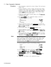
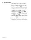
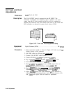
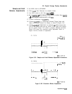
See Figure 3-86 for location of adjustment.
A3A8
ANALOG-TO-DIGITAL CONVERTER
(Beneath Cover)
R5
RE
GAIN OFFS
Figure 3-86.
Location of Analog-To-Digital Converter Adjustments
g. Remove short from
A3A8TP4
and A3A8TP5 or disconnect the
SMB snap-on short from
A3A8Jl.
h. Press (INSTR PRESET).
i. Press MARKER
c-1,
1498 (MHz), and
CSHIFT)
(SINGLE)
“.
j. Connect DVM to
A3A8TP5
and ground to
A3A8TP4.
Set DVM
for V de.
k. Connect output of the Low-Noise DC Supply to
A3A8Jl.
Adjust
the Low-Noise DC Supply for DVM indication of + 10.000
&.OOlV
dc.
3.140
Adjustments