


7. 3 MHz Bandwidth Filter Adjustments
25. Adjust
A4A7C13
PK for maximum peak-to-peak signal on Channel
2 display. See Figure 3-39 for location of adjustment. If unable to
achieve a “peak” in signal amplitude, increase or decrease value
of
A4A7C12.
Refer to
Table
3-3 for range of values.
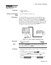
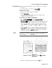
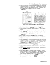
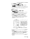
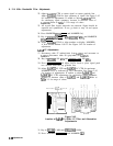
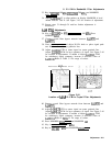
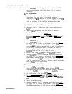
A4A7
3 MHz Bandwidth Filter
Figure 3-39. Location of 3 MHz Peak Adjustments
26. Move Channel 2 probe to A4A7TP3 (left side of
C32
SYM).
27. Adjust frequency synthesizer output frequency to peak Channel 1
display.
28. Adjust
A4A7C22
PK for maximum peak-to-peak signal on Channel
2 display. See Figure 3-39 for location of adjustment. If unable to
achieve a “peak” in signal amplitude, increase or decrease value
of
A4A7C21.
Refer to Table 3-3 for range of values.
29. Move Channel 2 probe to A4A7TPl (left side of
C41
SYM).
30. Adjust frequency synthesizer output frequency to peak Channel 1
display.
31. Adjust
A4A7C31
PK for maximum peak-to-peak signal on Channel
2 display. See Figure 3-39 for location of adjustment. If unable to
achieve a “peak” in signal amplitude, increase or decrease value
of
A4A7C30.
Refer to
‘Iable
3-3 for range of values.
32. Disconnect Channel 2 probe from A4A7TPl.
33. Adjust frequency synthesizer output frequency to peak Channel 1
display.
34. Adjust [REFERENCE
LEVEL_)
using step keys to place signal near top
CRT graticule line.
35. Adjust
A4A7C40
PK for maximum signal amplitude on the CRT
display. See Figure 3-39 for the location of adjustment. If unable
to achieve a “peak” in signal amplitude, increase or decrease
value of
A4A7C39.
Refer to Table 3-3 for range of values.
36. Disconnect Channel 1 probe from A4A7TP7. Disconnect
‘frequency synthesizer output from
A4A8Jl
and reconnect cable
97 (white/violet).
Adjustments 3-75