


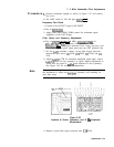
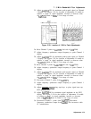
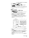

8. 21.4 MHz Bandwidth Filter Adjustments
10. Key in
CRESBW_)
1 MHz, and
ISPAN)
1 MHz.
11. Press MARKER
CPEAK
SEARCH], MARKER
a.
12. Key in
CREsBW)
100 kHz,
[-SPAN)
200 kHz, and MARKER
[PEAK SEARCH).
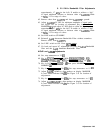
13. Adjust
A4A4R43
LC to align markers on display. MARKER A level
should indicate 1.00 X. See Figure 3-41 for location of adjustment.
14. Repeat steps 10 through 13 until no further adjustment is
necessary.
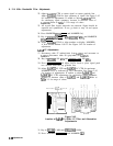
A4A4
XTAL Adjustments
15. Press MARKER
loFF).
Key in
CREsJ
30 kHz and
[FREQUENCY SPAN] 100 kHz.
16. Press [REFERENCE LEVEL) and adjust DATA knob to set signal peak
on screen two divisions from the top graticule line.
17. Connect crystal filter bypass networks between A4A4TPl and
A4A4TP2
and between A4A4TP4 and
A4A4TP5.
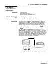
18. Adjust
A4A4C20
CTR to center signal on center graticule
line. Adjust
A4A4C9
SYM for best symmetry of signal. See
Figure 3-42 for location of adjustments. If unable to adjust SYM
for satisfactory signal symmetry, increase or decrease value of
A4A4ClO.
Refer to Table 3-3 for range of values.
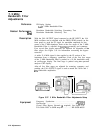
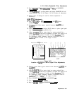
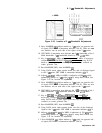
A4A4
Bandwidth Filter
A4A4
Figure 3-42.
Location of
A4A4
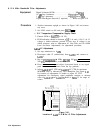
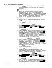
21.4 MHz Crystal Filter Adjustments
19. Remove crystal filter bypass network from between A4A4TP4 and
A4A4TP5.
20. Adjust
A4A4C74
CTR to center signal on center graticule line.
Adjust
A4A4C39
SYM for best symmetry of signal. See Figure 3-42
for location of adjustments. If unable to adjust
A4A4C39
SYM
for satisfactory signal symmetry, increase or decrease value of
A4A4C38.
Refer to Table 3-3 for range of values.
21. Remove crystal filter bypass network from between A4A4TPl and
A4A4TP2.
Adjustments
3.79