19 BUILT-IN I/O FUNCTION
19.1 High-speed Counter Function
117
19
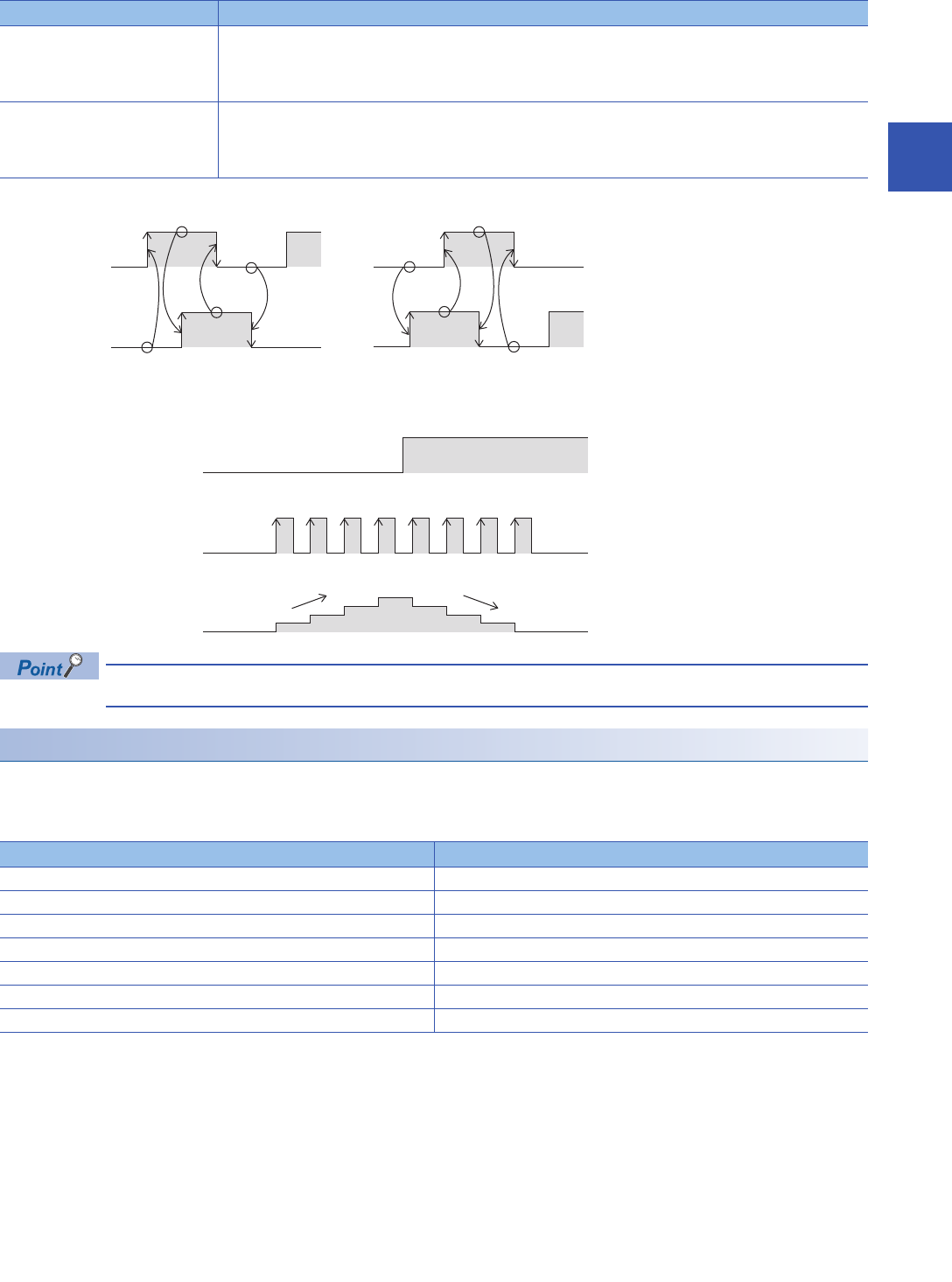
■2 phase, 2 input counter [4 edge count]
Counting method of 2 phase, 2 input counter [4 edge count] is as follows.
■Internal clock
Counting method of internal clock is as follows.
Under ordinary circumstances, the internal clock counts up/down by 1 MHz clock. External input is not used.
Maximum frequency
The maximum frequency that each type of counter can count is as follows.
For details concerning maximum frequency by input assignment, refer to Page 120 Input assignment-wise / maximum
frequency for high-speed counters.
Up/down counter Counter timing
At up-counting 1 count up when phase B input is OFF and phase A input switches OFFON
1 count up when phase A input is ON and phase B input switches OFFON
1 count up when phase B input is ON and phase A input switches ONOFF
1 count up when phase A input is OFF and phase B input switches ONOFF
At down-counting 1 count down when phase A input is OFF and phase B input switches OFFON
1 count down when phase B input is ON and phase A input switches OFFON
1 count down when phase A input is ON and phase B input switches ONOFF
1 count down when phase B input is OFF and phase A input switches ONOFF
Counter type Maximum frequency
1 phase, 1 input counter (S/W) 200 KHz
1 phase, 1 input counter (H/W) 200 KHz
1 phase, 2 input counter 200 KHz
2 phase, 2 input counter [1 edge count] 200 KHz
2 phase, 2 input counter [2 edge count] 100 KHz
2 phase, 2 input counter [4 edge count] 50 KHz
Internal clock 1 MHz (fixed)
-1 -1-1+1+1 +1 +1
B-phase input
A-phase input
At down-countingAt up-counting
-1
ON
ON
OFF
OFF
Current value
Up counting Down counting
Internal clock (1 MHz)
Count direction switching bit


