


182
19 BUILT-IN I/O FUNCTION
19.3 Pulse Width Measurement Function
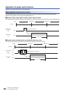
Period maximum value
The maximum value of the period is stored.
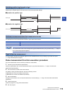
• When logic switching is set to positive logic, the difference from rising edge to rising edge.
• When logic switching is set to negative logic, the difference from falling edge to falling edge.
• The maximum value of the period can be changed only by the HCMOV instruction.
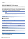
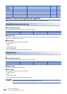
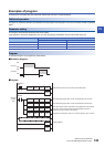
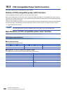
■Corresponding devices
The device numbers corresponding to each channel are as follows.
■Update timing, clear timing
Same as the rising edge ring counter value (Page 180 Rising edge ring counter value)
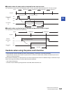
Period minimum value
The minimum value of the period is stored.
• When logic switching is set to positive logic, the difference from rising edge to rising edge.
• When logic switching is set to negative logic, the difference from falling edge to falling edge.
• The minimum value of the period can be changed only by the HCMOV instruction.
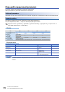
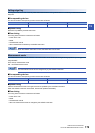
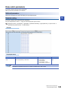
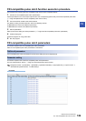
■Corresponding devices
The device numbers corresponding to each channel are as follows.
■Update timing, clear timing
Same as the rising edge ring counter value (Page 180 Rising edge ring counter value)
Cautions when using the pulse width measurement function
• When the HCMOV instruction is used, the latest ring counter value, pulse width, cycle, maximum value, and minimum value
can be obtained.
• The measurement mode can be changed using the special relays. Note, however, that the measurement mode cannot be
changed during pulse width measurement. To change the measurement mode, stop pulse width measurement, change the
measurement mode and then resume measurement.
• Pulse measurement is possible only while in RUN status. Pulse width measurement is stopped by RUNPAUSE and
RUNSTOP.
CH1 CH2 CH3 CH4
SD5033, SD5032 SD5053, SD5052 SD5073, SD5072 SD5093, SD5092
CH1 CH2 CH3 CH4
SD5035, SD5034 SD5055, SD5054 SD5075, SD5074 SD5095, SD5094