128
19 BUILT-IN I/O FUNCTION
19.1 High-speed Counter Function
Precautions
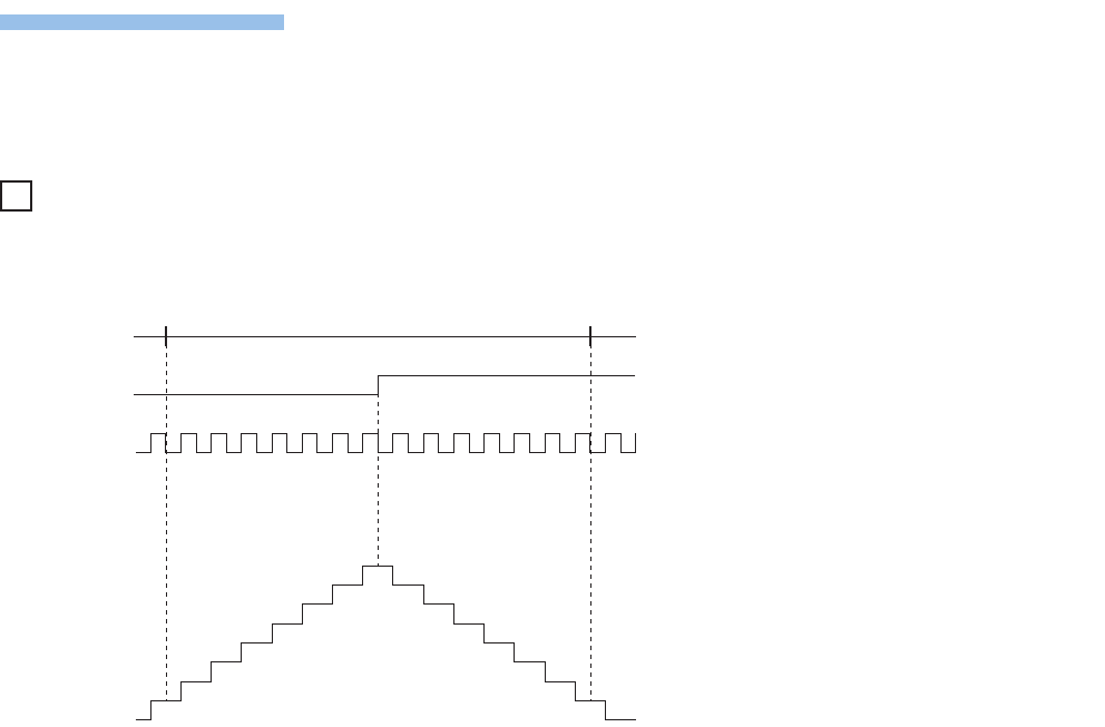
■Count direction switch during measurement
The pulse density measurement mode calculates pulse density based on difference in measuring unit time of the current
value of high-speed counters. You should therefore note that the input number of pulses may differ from the measurement
value when count direction of a high-speed counter is switched within the same measuring unit time.
Ex.
When pulse density is measured, 14 pulses are input within measuring unit time, but the current value of the high-speed
counter remains "0", as shown in the following figure. As a result, pulse density is "0" for this measuring unit time.
■Operation when counting in the minus direction
Pulse density can also be measured when pulses are input in the direction whereby current value of high-speed counter is
reduced.
■Operation at overflow of high-speed counter current value
Pulse density measurement can continue even when current value of high-speed counter overflows during measurement.
■Relationship with the SPD instruction
Measurement time specified by operand of the SPD instruction is overwritten in the special register for measuring unit time
used by the pulse density measurement function. Measurement results of the SPD instruction are also stored in the special
register of measurement results.
If pulse density measurement has already been started by the HIOEN instruction, the SPD instruction cannot be used for the
same channel.
Inversely, if pulse density is currently being measured by the SPD instruction, pulse density measurement cannot be started
for the same channel.
■Other precautions
There are common precautions when using high-speed counters. For details, refer to Page 163 Precautions when using
high-speed counters.
Measurement
intervals
Direction
switching
Count input
Current value
10
9
8
7
6
5
4
3
2
1
0


