


19 BUILT-IN I/O FUNCTION
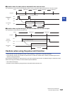
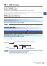
19.7 PWM Function
195
19
PWM output parameters
This section explains the PWM output parameters.
Set the PWM output parameters in GX Works3.
Outline of parameters
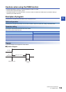
PWM output parameters are output destination, pulse width/cycle unit, output pulse logic, pulse width, and period.
Parameter setting
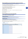
This section explains how to set the PWM output parameters.
Set the output destination, pulse width/cycle unit, output pulse logic, pulse width, period, etc. of the channel to be used.
Navigation window [Parameter] [FX5UCPU] [Module Parameter] [High Speed I/O] “Output Function"
“PWM" "Detail Setting"
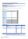
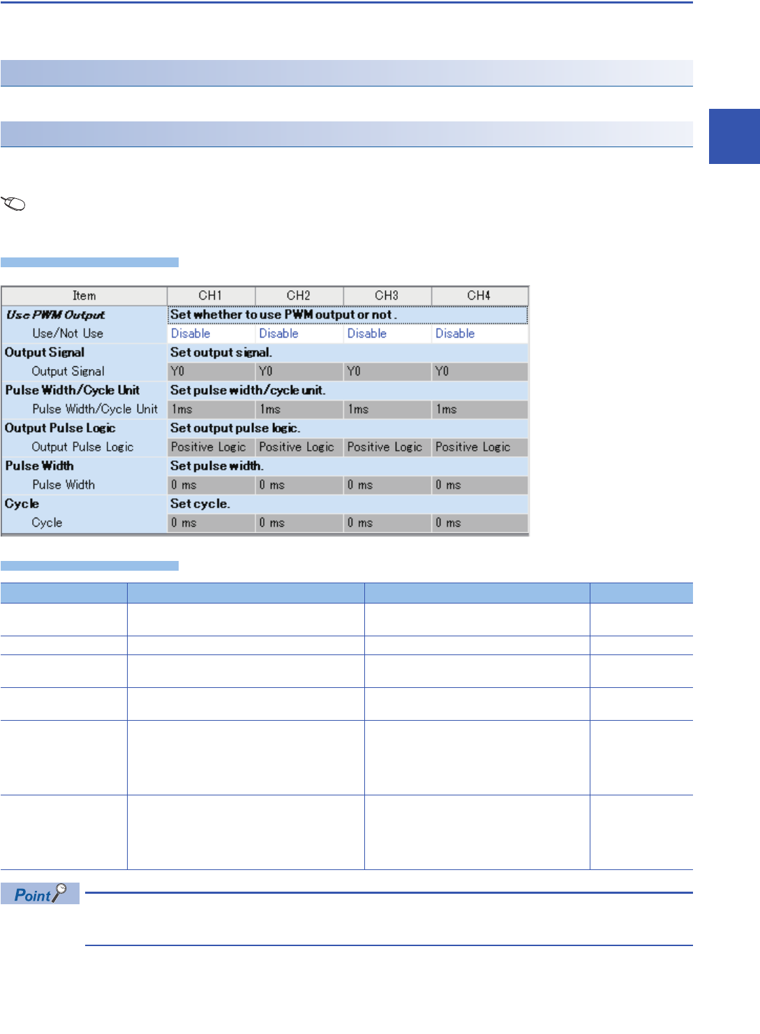
Window
Displayed items
The items specified in the parameters are stored in special devices when the CPU module is set from STOP
to RUN.
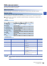
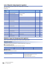
Item Description Setting range Default
Use PWM Output Set whether to use PWM output or not. • Disable
• Enable
Enable
Output Signal Set the output destination device of output signal. Y0 to Y7
Pulse Width/Cycle Unit Set pulse width/cycle unit. • 1ms
• 1micro-s (s)
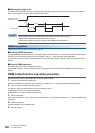
Output Pulse Logic Sets output pulse logic. • Positive Logic
• Negative Logic
Pulse Width Sets the ON/OFF width of the pulse. • When pulse width/period unit is set to 1 ms
1 to 2147483 ms
• When pulse width/period unit is set to 1 micro-s
(s)
1 to 2147483647 micro-s (s)
Cycle Sets cycle. • When pulse width/cycle unit is set to 1 ms
1 to 2147483 ms
• When pulse width/cycle unit is set to 1 micro-s
(s)
1 to 2147483647 micro-s (s)