


56
9 PID CONTROL FUNCTION
9.3 How to Use PID Instruction
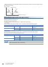
Expression for calculating the measured value (after the filter) in sampling at this time
(PVnf)
The value "PVnf" is obtained from the following expression based on the read measured value.
Measured value after filter: PVnf = PVn+L (PVnf-1-PVn)
9.3 How to Use PID Instruction
This instruction executes PID control which changes the output value according to the input variation.
For details on the PID instruction, refer to the following manual.
MELSEC iQ-F FX5 Programming Manual (Instructions, Standard Functions/Function Blocks)
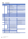
Setting data
■Descriptions, ranges, and data types
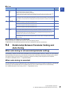
■Applicable devices
*1 Only D, SD, R can be used.
Processing details
• Once the target value (s1), measured value (s2) and PID parameters (s3) to (s3)+6 are set and the program is executed,
the operation result (MV) is transferred to the output value (d) at every sampling time. The sampling time is specified by
(s3)
PVn: Measured value in sampling at this time
L: Filter coefficient
PVnf-1: Measured value in previous cycle (after filter)
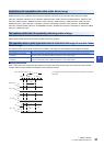
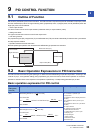
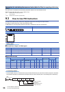
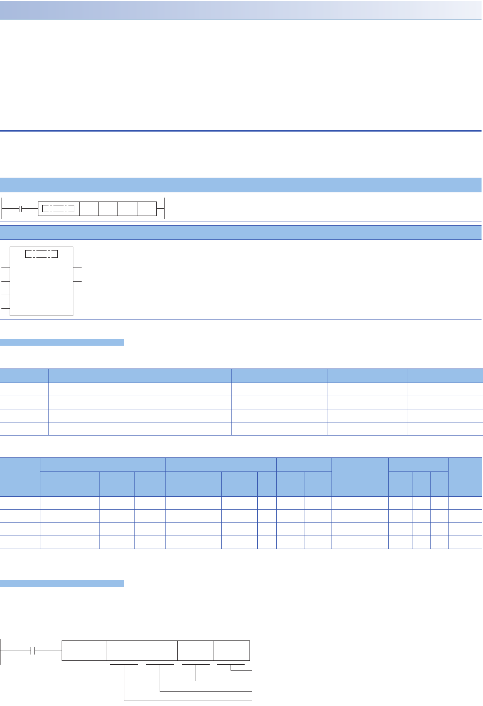
Ladder diagram Structured text
ENO:=PID(EN,s1,s2,s3,d);
FBD/LD
Operand Description Range Data type Data type (label)
(s1) Device number storing the target value (SV) -32768 to +32767 16-bit signed binary ANY16
(s2) Device number storing the measured value (PV) -32768 to +32767 16-bit signed binary ANY16
(s3) Device number storing PID parameters 1 to 32767 16-bit signed binary ANY16
(d) Device number storing the output value (MV) -32768 to +32767 16-bit signed binary ANY16
Operand Bit Word Double word Indirect
specification
Constant Others
X, Y, M, L, SM,
F, B, SB, S
U\G T, ST,
C, LC
T, ST, C, D,
W, SD, SW, R
U\G Z LC LZ K, H E $
(s1)
*1
(s2)
*1
(s3)
*1
(d)
*1
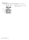
(s1) (s2) (s3) (d)
EN ENO
ds1
s2
s3
Command input
Target value (SV)
Measured value (PV)
Parameters
Output value (MV)
PID (s1) (s2) (s3) (d)