


19 BUILT-IN I/O FUNCTION
19.3 Pulse Width Measurement Function
175
19
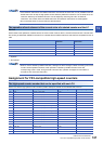
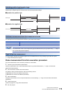
Switching positive logic/negative logic
The pulse input logic can be switched.
Positive logic or negative logic can be set for each channel with parameter settings.
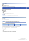
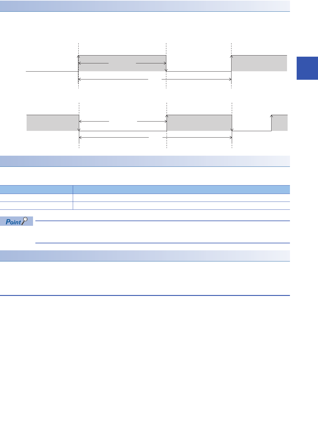
■Operation for positive logic
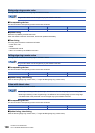
■Operation for negative logic
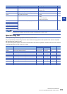
Continuous measurement/one-time measurement mode
The pulse width measurement mode can be set.
The table below shows the measurement modes for pulse width measurements.
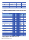
The measurement mode can be changed during pulse measurements by using a special relay. (Page 177
List of special relays/special registers)
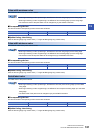
Signal delay time measurement
In a user program, the delay time between signals can be calculated from the rising or falling ring counters of 2 inputs.
(Page 183 Examples of program)
Pulse measurement function execution procedure
The pulse measurement function execution procedure is shown below.
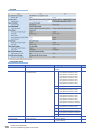
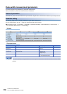
1. Check the pulse measurement specifications.
Check the specifications such as the measurement frequency of pulse measurements. (Page 174 Pulse width
measurement specifications)
2. Connect the CPU module to the external device.
For details on wiring to external devices, refer to the following manual
MELSEC iQ-F FX5U User's Manual (Hardware)
MELSEC iQ-F FX5UC User's Manual (Hardware)
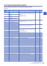
3. Set the parameters.
Configure the parameters such as the pulse measurement channel settings. (Page 176 Pulse width measurement
parameters)
4. Create the program.
Create the program for using pulse measurements.
5. Run the program.
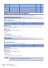
Mode Description
1 time measurement mode Measures the pulse width and period only once from the start of the measurement.
Always measurement mode Constantly measures the pulse width and period.
Pulse input
Pulse width
Cycle
Pulse input
Pulse width
Cycle