


214
21 DEVICES
21.2 User Devices
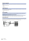
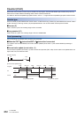
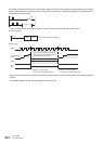
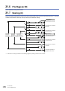
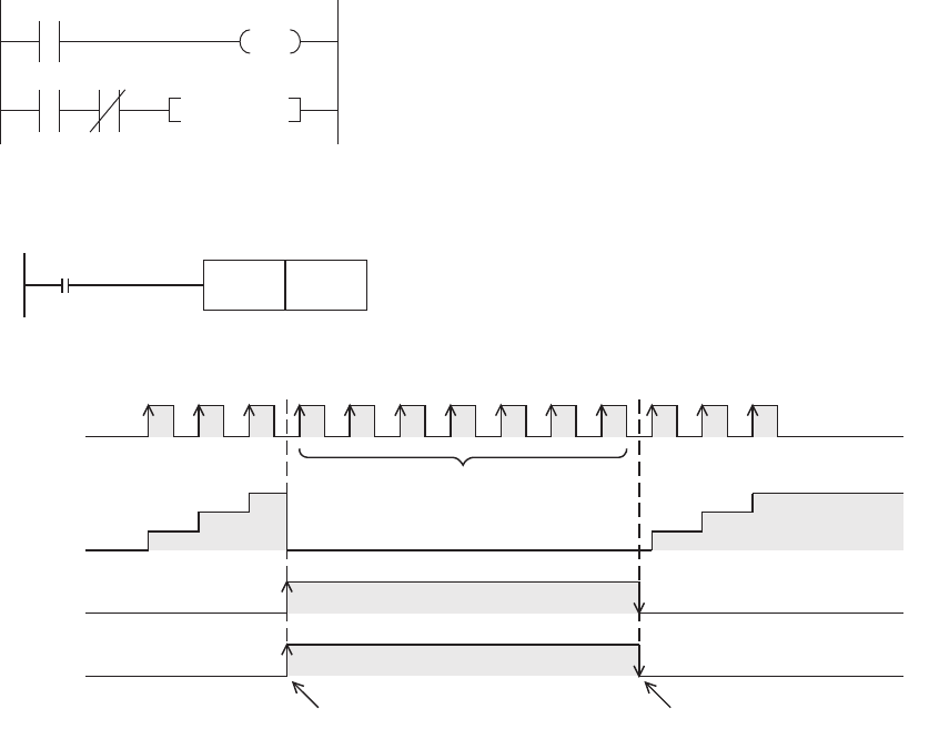
To handle this, arrange so that C0 coil is not turned OFF while OUT C0 instruction execution condition (M0) is ON, by inserting
the NC contact execution condition of the OUT C0 instruction in the execution condition of the RST C0 instruction as shown
by the following circuit example.
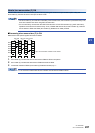
• When a counter is reset by the RST instruction, it cannot count until the RST instruction is set to OFF.
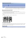
• When the counter is set as a latch device, the current value of a counter, output contact operation, and the reset image are
latched.
• If the ZRST instruction is used, the RST image of a counter is reset.
C0
M0 K10
M0C0
RST C0
X000
Current value
of C0
1
2
3
The current value does not change
even if pulses are input because the
C0 reset instruction is valid.
C0 remains reset
"RST C0" is set to ON
because the contact turns ON.
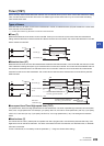
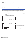
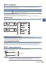
X010
RST
C0
1
2
3
"RST C0" is set to OFF
because the contact turns OFF.
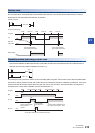
[Timing chart]
[Program example]
X010
RST C0
C0 is reset while X010 turns ON.