19 BUILT-IN I/O FUNCTION
19.7 PWM Function
193
19
19.7 PWM Function
This chapter explains the PWM function.
Outline of PWM output
The CPU module has a built-in PWM function, which allows PWM output on up to four channels.
For PWM output, the output channel assignment, pulse/cycle units, output pulse logic, pulse width, cycle, etc. are set using
parameters, and the HIOEN instruction is used to start/stop pulse output.
Also, the regular PWM instruction can be used.
PWM output specifications
The PWM output specifications are explained below.
Number of output channels
Up to four channels can be used for PWM output.
Output Y0 to Y7 can be selected for each channel in parameters.
Outputs (Y) assigned for PWM output in parameter settings cannot be used by the positioning function.
Pulse output performance
The cycle and pulse width are shown below.
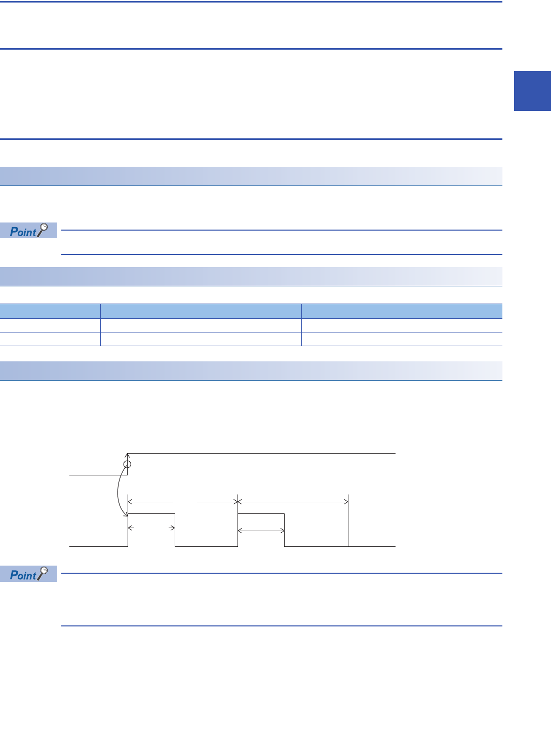
Relationship between cycle and pulse width
The relationship between period and pulse width is shown below.
■When positive logic is set
The relationship between the period and pulse width when the output pulse logic at start of pulse output is set to "positive
logic" is shown below. (The pulse width is called the "ON width".)
• When positive logic is set, PWM output begins from output ON.)
• Pulse output is stopped at the specified number of pulses.
• Pulse output stops in the output (Y) status of before PWM output was started.
Output number Minimum period Minimum pulse width
Y0 to Y3 5 s2 s
Y4 to Y7 400 s200 s
Output pulse
Cycle
PWM output start
(command input)
ON width


