


246
APPENDIX
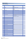
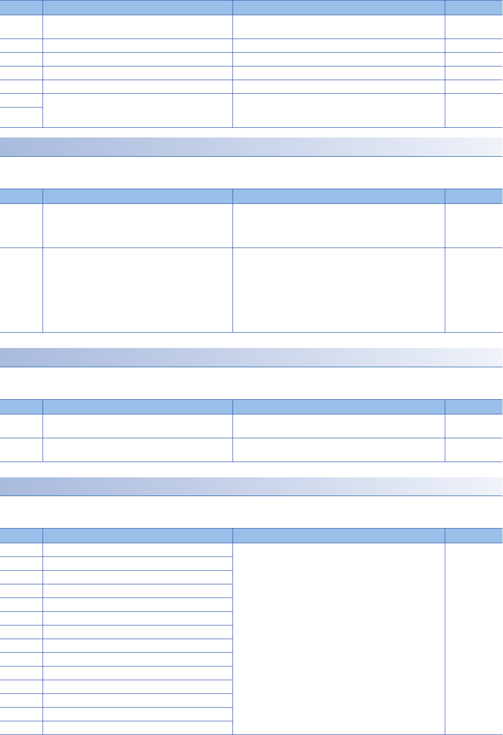
Appendix 2 Special Register List
Instruction related
The special registers related to instruction execution are shown below.
R: Read only, R/W: Read/Write
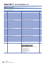
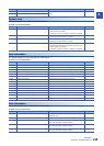
Mask pattern of interrupt pointers
The special registers for the mask pattern of interrupt pointers are shown below.
R: Read only, R/W: Read/Write
FX dedicated
The special registers dedicated to FX are shown below.
R: Read only, R/W: Read/Write
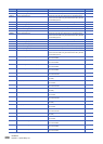
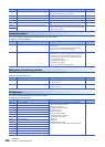
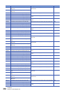
SD609 SD memory card capacity This register stores the drive 2 storage capacity (unit: 1 K byte).
(Free space value after formatting is stored.)
R
SD610 SD memory card free space capacity This register stores the free space value in drive 2 (unit: 1 K byte). R
SD611 SD memory card free space capacity This register stores the free space value in drive 2 (unit: 1 K byte). R
SD612 SD memory card free space capacity This register stores the free space value in drive 2 (unit: 1 K byte). R
SD613 SD memory card free space capacity This register stores the free space value in drive 2 (unit: 1 K byte). R
SD634 Index for the number of data memory write operations Stores an index for the number of write operations to data
memory currently. However, the index does not equal the actual
number of write operations.
R
SD635
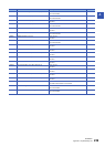
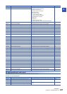
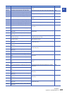
No. Name Description R/W
SD757 Current interrupt priority This register stores the interrupt priority of the interrupt program
being executed.
1 to 3: The interrupt priority of interrupt program executed.
0: The interrupt is not executed. (default value)
R
SD758 Interrupt disabling for each priority setting value This register stores the disable interrupt priority according to the
disable interrupt instruction (DI), disable interrupt after the setting
priority instruction (DI), and enable interrupt instruction (EI).
1: Disable interrupt priority 1 or less. (Disable interrupt of all
priority) (default value)
2: Disable interrupt priority 2 or 3.
3: Disable interrupt priority 3.
0: No priority. (Enable interrupt of all priority)
R
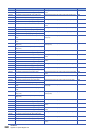
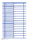
No. Name Description R/W
SD1400 Mask pattern I This register stores the IMASK instruction mask pattern I.
b15 to b0: I15 to I0
R/W
SD1401 Mask pattern I This register stores the IMASK instruction mask pattern I.
b15 to b0: I31 to I16
R/W
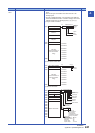
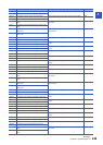
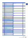
No. Name Description R/W
SD4110 Error code 1 details This register stores the self-diagnosis error code details.
• Module position [Low order 8 bit]
0H: Built-in high-speed I/O
41H: Built-in serial communication
42H: Built-in analog
60H: Expansion board
71 to 76H: Expansion adapter
• Function No. [Higher order 8 bit]
0: System/Sequence operation
1: Built-in A/D
2: Built-in D/A
10: Built-in positioning, PWM
20: Built-in high-speed counter, Pulse width measurement
R
SD4111 Error code 2 details
SD4112 Error code 3 details
SD4113 Error code 4 details
SD4114 Error code 5 details
SD4115 Error code 6 details
SD4116 Error code 7 details
SD4117 Error code 8 details
SD4118 Error code 9 details
SD4119 Error code 10 details
SD4120 Error code 11 details
SD4121 Error code 12 details
SD4122 Error code 13 details
SD4123 Error code 14 details
No. Name Description R/W