


Operating Instructions Teledyne API – T101 Operation Manual
102
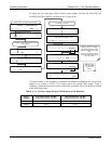
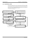
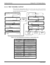
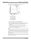
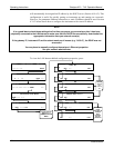
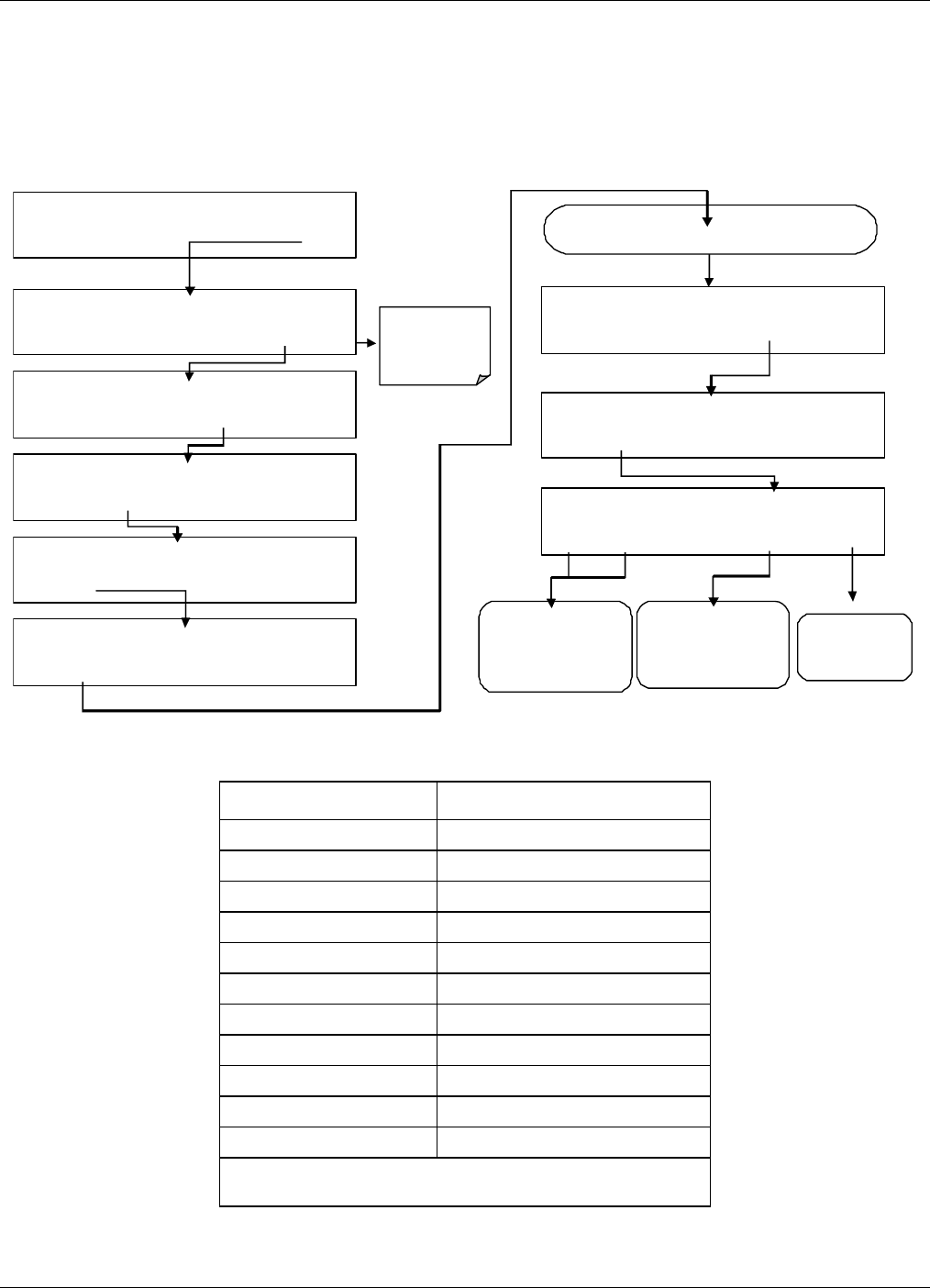
4.6.9. TEST CHANNEL OUTPUT
When activated, output channel A4 can be used to report one of the test functions
viewable from the SAMPLE mode display. To activate the A4 channel and select a test
function, follow this button sequence :
SAMPLE RANGE = 500.0 PPB H2S =XXX.X
< TST TST > CAL SETUP
SAMPLE ENTER SETUP PASS :
8
18
8 1 8 ENTR EXIT
SETUP X.X PRIMARY SETUP MENU
CFG DAS RNGE PASS CLK MORE EXIT
DIAG SIGNAL I / O
NEXT ENTR EXIT
DIAG AN ALOG OUTPUT
PREV NEXT ENTR EXIT
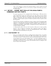
DIAG TCHN TEST CHANNEL: NONE
NEXT ENTR EXIT
DIAG TEST CHAN OUTPUT
PREV NEXT ENTR EXIT
EXIT returns
to the main
SAMPLE
display
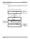
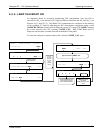
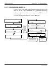
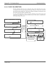
Continue to press NEXT until …
DIAG TCHN TEST CHANNEL: PMT READING
PREV NEXT ENTR EXIT
Press PRE
V
or NEX
T
to move through the
list of available
parameters
(Table 6-13)
Press EXIT to
return to the
DIAG menu
Press ENTR to select
the displayed
parameter activating
the test channel.
SETUP X.X SECONDARY SETUP MENU
COMM VARS DIAG EXIT
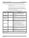
Table 4-15. Test Parameters Available for Analog Output A4
TEST CHANNEL TEST PARAMETER RANGE
1
NONE Test channel is turned off
PMT READING 0-5000 mV
UV READING 0-5000 mV
SAMPLE PRESSURE 0-40 in-Hg-A
SAMPLE FLOW 0-1000 cm³/min
RCELL TEMP 0-70° C
CHASSIS TEMP 0-70° C
IZS TEMP 0-70° C
PMT TEMP 0-50° C
CHASSIS TEMP 0-70° C
HVPS VOLTAGE 0-5000 V
1
This refers to the voltage range of the parameter and
not the output signal of the test channel.
07266B DCN6485