


Model T101 Instruction Manual Principles Of Operation
255
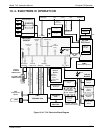
10.3.2. MULTIGAS MEASUREMENT & H
2
S SO
2
SWITCHING
VALVE.
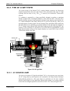
When activated for operation the multigas measurement mode allows the instrument to
measure either or both H
2
S or SO
2
via a Teflon
®
switching valve. This valve, under CPU
control via the I
2
C buss and the relay board, directs the sample gas stream either through
the SO
2
scrubber and H
2
S SO
2
converter (H
2
S measurement mode) or directly to the
sample chamber bypassing the H
2
S SO
2
converter, allowing the analyzer to measure
SO
2
. The cycle for this operation is
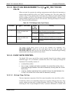
Table 10-1. T101 Multigas Valve Cycle-Phases
Gas Mode H
2
S SO
2
Valve Status
Default
Time
Settings
Activity
0 – 3
minutes
Wait period. Ensures sample chamber has
been flushed of previous gas.
H
2
S Gas stream directed
through scrubber and
converter
3 – 10 m Analyzer measures florescence in sample
chamber
0 – 3
minutes
Wait period (dwell time). Ensures sample
chamber has been flushed of previous gas.
SO
2
Gas stream bypasses
through scrubber and
converter
3 – 10 m Analyzer measures florescence in sample
chamber
Cycle repeats every ~20Minuites
The timing of the above cycle is set by two variables (see Appendix A-2),
MEASURE_PERIOD, which sets the total dwell time for each gas mode, and
MEASURE_DELAY which sets the wait period before the instrument begins making
measurements after the gas mode has been switch.
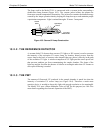
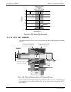
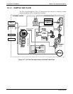
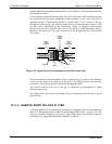
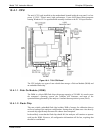
10.3.3. FLOW RATE CONTROL
The Model T101 uses a special flow control assembly located in the exhaust vacuum
manifold (Figure 10-7) to maintain a constant flow rate of the sample gas through the
instrument. This assembly consists of:
a critical flow orifice
two o-rings: Located just before and after the critical flow orifice, the o-
rings seal the gap between the walls of assembly housing and the critical
flow orifice.
a spring: Applies mechanical force needed to form the seal between the
o-rings, the critical flow orifice and the assembly housing.
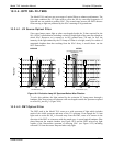
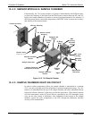
10.3.3.1. Critical Flow Orifice
The most important component of this flow control assembly is the critical flow orifice.
Critical flow orifices are a remarkably simple way to regulate stable gas flow rates. They
operate without moving parts by taking advantage of the laws of fluid dynamics. By
restricting the flow of gas though the orifice, a pressure differential is created. This
07266B DCN6485