


Getting Started Teledyne API – T101 Operation Manual
38
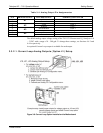
SPAN CAL
ZERO CAL
SPAN CAL
ZERO CAL
CONTROL IN
A B C D E F U
+
CONTROL IN
A B C D E F U
+
-
+
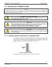
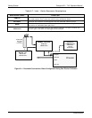
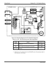
Local Power Connections
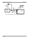
External Power Connections
5 VDC Power
Supply
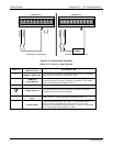
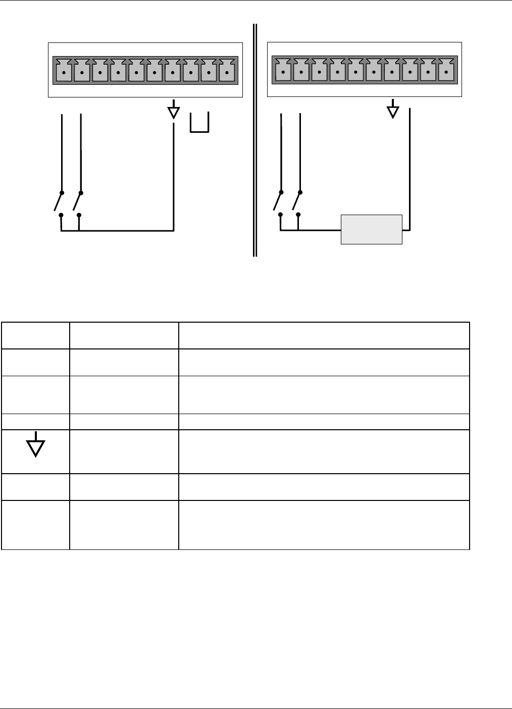
Figure 3-10. Control Input Connector
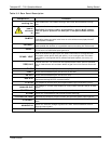
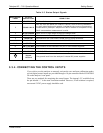
Table 3-6. Control Input Signals
INPUT #
STATUS
DEFINITION
ON CONDITION
A
REMOTE ZERO CAL
The analyzer is placed in Zero Calibration mode. The mode
field of the display will read ZERO CAL R.
B
REMOTE
LO SPAN CAL
The analyzer is placed in low span calibration mode as part
of performing a low span (midpoint) calibration. The mode
field of the display will read LO CAL R.
C, D, E & F SPARE
Digital Ground
The ground level from the analyzer’s internal DC power
supplies (same as chassis ground)
U External Power
input
Input pin for +5 VDC required to activate pins A – F.
+
5 VDC output
Internally generated 5V DC power. To activate inputs A – F,
place a jumper between this pin and the “U” pin. The
maximum amperage through this port is 300 mA (combined
with the analog output supply, if used).
07266B DCN6485